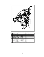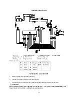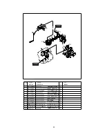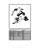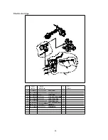
WIRING DIAGRAM
7
6
W
9
Y/R
8
Y/R
Y
Y
B
W
W
B
B
R
/
W
B
8
5
3
Br L
L
B r
Y O B
B
O
Y
10
4
2
G
G
G
L
L
L
L
L
B
R
B
1
B
R
/
W
○
1
C D I
○
4
Oil press switch
○
7
Engine stop switch
○
10
Spark plug
○
2
Lighting coil
○
5
Pulsed coil
○
8
Grounding wire
○
3
Charge coil
○
6
Ignition coil
○
9
Oil alert light
Wire beam color:
W
White
O
Orange
Y/R
Yellow/Red
B
Black
L
Blue
R/W
Red/White
R
Red
G
Green
Y
Yellow
Br
Brown
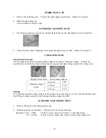
SPARK PLUG IGNITION
1. Remove spark plug cap from spark plug.
2. Connect the ignition tester to the spark plug cap.
3. Start the engine, and observe the sparks through the discharge window of the tester.
WARNING:
Do not touch any joint part of the lead wire of the tester. Keep away from inflammable gas or
liquid, to prevent accident resulting from spark ignition.
35
Содержание F15/F9.9BM
Страница 1: ...PARSUN OUTBOARD ENGINE SERVICE MANUAL F15 F9 9BM F15 F9 9W SUZHOU PARSUN POWER MACHINE CO LTD...
Страница 13: ...DETECTION DEVICE Digital tachometer Digital circuit tester Peak voltage adaptor 7...
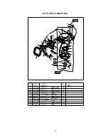
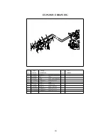
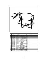
Страница 36: ...EXPLOSIVE DRAWING REMARKS PART NO DESCRIPTION 30...
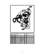
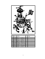
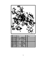
Страница 37: ...REMARKS DESCRIPTION PART NO 110 Nm O M6x20 mm 8Nm O 18 Nm 31...
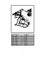
Страница 38: ...PART NO DESCRIPTION REMARKS 18 Nm O M6x20 mm 8Nm O 110 Nm 32...
Страница 39: ...Electric start type PART NO DESCRIPTION REMARKS 30 Nm 33...
Страница 40: ...PART NO DESCRIPTION REMARKS 34...

