


14 GB / IE / NI
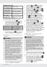
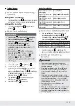
Charging status LeDs
Green LED lights up
without battery pack
Charger ready
Green LED lights up
with battery pack
Battery pack fully charged
Red LED lights up
with battery pack
Battery pack charging
Red LED flashes with
battery pack
Battery pack defect
Green LED flashes
with battery pack
Battery pack too cold or
warm
Q
Checking the battery level
o
Press the battery level button
23
to check the
charging level of the battery pack
4
. The
status / remaining charge will be shown on
the battery level indication light
21
.
3 Red LEDs light up maximum charging level
2 Red LEDs light up medium charging level
1 Red LEDs lights up low charging level
o
Charge the battery pack
4
before operation
when it is at medium or low charging level.
Q
Attaching / removing the saw
blade
WArNING!
u
Always remove the battery pack from the
product before changing the saw blade in
order to avoid switching it on accidentally.
u
Always use the correct accessories according
to the intended use! Observe the technical
requirements of this product (see section
Technical data) when purchasing and using
accessories!
u
Accessories can be sharp and become hot
during use! Handle them carefully! Wear
safety gloves when handling accessories in
order to avoid injuries like burns and cuts!
u
Never press the spindle lock whilst the
spindle is rotating!
u
The arrow on the accessory must correspond
to the arrow showing the direction of rotation
(running direction shown on the product).
u
Ensure that the accessory is suitable for the
rotational speed of the product.
1. Set the cutting depth to the minimum position,
0 mm (see “Setting the cutting depth”).
2. Swing the blade guard
15
back using the
release lever
19
and put the product down.
3. Press the spindle lock button
8
until it
engages. Keep the button pressed and loosen
the clamping screw
18
with the hex key
9
.
4. Remove the clamping screw
18
, washer
17
and the clamping flange
16
(Fig. D).
5. Remove saw blade, if necessary.
6. Clean the flanges and spindle from dust.
7. Place a suitable saw blade, the clamping
flange
16
, the washer
17
and the clamping
screw
18
onto the spindle. The arrow on
the saw blade must correspond to the arrow
showing the direction of rotation (running
direction shown on the product).
8. Press the spindle lock button
8
until it
engages. Keep the button pressed and tighten
the clamping screw
18
with the hex key
9
.
9. Turn the saw blade by hand to test if it is
rotating smoothly. The blade should not flutter.
10. Switch the product on and let it run idle for
about one minute, to confirm that the saw blade
has been installed properly. Switch off the
product and re-fit the saw blade as described,
should there any abnormal vibration or
excessive noise occur.
Q
Attaching / removing a dust
extraction device
WArNING!
u
During operation fine dust will be generated!
Some dusts are highly inflammable and
explosive! Always attach a dust extraction
device when using this product in order to
keep the working area clean! Wear a dust
mask when operating this product! Dust can
be harmful to health! Especially dust and chips
of wood that has been treated, e.g. with wood
preservative or a stain!
u
Do not smoke during operation, keep heat
sources and open flames out of the working
area!
1. Connect an approved dust and chip extraction
device to the vacuum outlet for dust extraction
20
.
Q
Checking the blade guard
1. Pull the release lever for the blade guard
19
back as far as the stop. The blade guard
15
must move freely without jamming and
must spring back into its starting position
automatically when the release lever for the
blade guard
19
is released.


