background image

www.parksafegroup.com


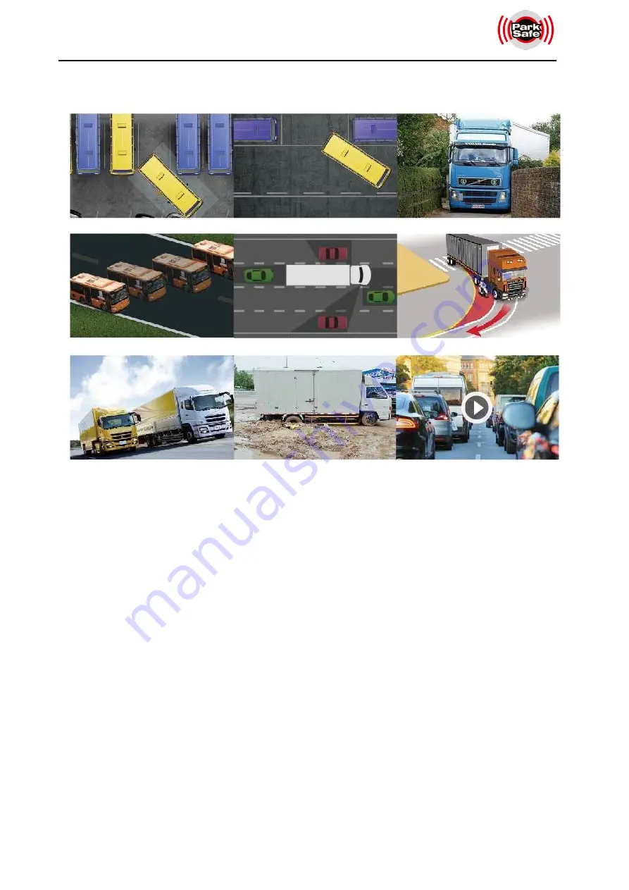
2.2 Application 

2.3 Features 

1)

Panoramic image.

2)

Blending seamless stitching.

3)

360° view.

4)

Wide surrounding field of vision.

5)

Auto switch to reversing image when reverse wire is triggered.

6)

Auto switch to left / right image when left / right wire is triggered.

7)

Installation guide with pictures.

8)

Automatic plane correction.

9)

Video recording.

10)

Adjustable angle of four overlapping areas.

11)

Distance mark for reversing.

Reverse Parking 

Side Parking 

Narrow Road 

Diversion Assistance 

Blind Area 

Congested Road 

Steep slope 

Road Trap 

    Driving Record 

Содержание FHD 360

Страница 1: ...www parksafegroup com Operating Instructions FHD 360 Vision System Please read this manual thoroughly before operating the unit and keep it for future reference V1 0 ...

Страница 2: ...www parksafegroup com Please read this manual thoroughly before operating the unit and keep it for future reference V1 0 ...

Страница 3: ...Features 3 2 1 Basic Features 3 2 2 Application 4 2 3 Features 4 2 4 Standard Configuration 5 2 5 Wiring Diagram 5 3 Specification 6 3 1 Main Control Box Video Parameter 6 3 2 Main Control Box Working Environment Parameter 6 3 3 Camera Parameter 6 4 Operation Instruction of Remote Control 8 5 Operation Instruction Of Main Menu Interface 9 ...

Страница 4: ...th excessive vibration or subject to severe impacts 6 Never puncture scratch or use abrasive cleaning materials on this device 7 Do not place cables where they may be pinched or stepped on 8 The Control Box is not designed to be waterproof Operating Precautions 1 The device can be powered by a 12 or 24 volt automotive battery or vehicle electrical system 2 Make sure all cables are connected proper...

Страница 5: ...e Refer servicing to qualified service personnel CAUTION Any changes or modifications not expressly approved in this manual may invalidate your warranty and necessitate expensive repairs This symbol is intended to alert the user to the presence of uninsulated dangerous voltage within the product s enclosure that may be of sufficient magnitude to constitute risk of electric shock to persons This sy...

Страница 6: ... to composite high accuracy seamless images 3 Support 2pcs x 128GB SD cards for storage Caution It is suggested that SD card being removed after power is cut off Do not remove the SD card when the device is powered on 4 Low cost calibration tools simplified calibration procedures 5 Maximum 4CH 1080P 30fps or 4CH 1080P 25fps video resolution 6 FHD 1080P video output 7 Camera internal and peripheral...

Страница 7: ...when reverse wire is triggered 6 Auto switch to left right image when left right wire is triggered 7 Installation guide with pictures 8 Automatic plane correction 9 Video recording 10 Adjustable angle of four overlapping areas 11 Distance mark for reversing Reverse Parking Side Parking Narrow Road Diversion Assistance Blind Area Congested Road Steep slope Road Trap Driving Record ...

Страница 8: ...n Item Configuration Quantity 1 Control box 1 2 FHD Eye fish vamera 4 3 34 button remote control 1 4 Power cable 1 5 Harness for cameras 1 6 Video signal cable and trigger harness 1 7 20M extension cable 4 8 Wi Fi extension cable 1 2 5 Wiring Diagram ...

Страница 9: ...oding Max 4CH 1080P H 264 recode Video Stream 4M 2M 3 2 Main Control Box Working Environment Parameter Parameter Parameter Range Working Voltage 10 32V Working Voltage Range for External Trigger Signals 10 32V Working Electric Current 2A 12V Working Temperature Range 20 70 Storage Temperature 40 85 Working Humidity 10 95 3 3 Camera Parameter Parameter Parameter Range Image Device 1 2 9 CMOS Frame ...

Страница 10: ...w parksafegroup com 7 Video Output 1 0Vp p 75Ohm White Balance Auto Viewing Angle 190 H Power Supply 12V Working Temperature Range 20 70 RH95 MAX Storage Temperature 40 85 RH95 MAX Waterproof Rating IP69K ...

Страница 11: ...n main interface Or operate plus minus in menu Interface Up Down button Shift image channel to front back view Or switch the left right option in menu interface SHIFT Shift current display mode to quad view in main menu interface Or switch options in menu interface POWER Turn on off video display Number button 0 9 Numeric entry button for input box Main interface view switch button CLEAR Delete bu...

Страница 12: ... Operation Instruction of Main Menu Interface 5 1 User Administration Login Feature Description Input password default password is 88888888 Login confirmation Modify password ESC key return to the last menu 5 2 Modify Password ...

Страница 13: ...to discard password modification 5 3 Main Menu Interface Feature Description User Setup User setup including basic function setting DVR setting display setting network setting etc Storage Storage management user can view the SD card U disk usage and format them AVM Including calibration calibration file import and export vehicle model switching view settings and other functions Video Record manage...

Страница 14: ... to check and upgrade the version of CPU and MCU 5 3 1 User Setup Interface as shown below 2D Mode 3D Mode Feature Description Basic Setup Basic setup interface Time Time setting interface DVR Basic recording setting and recording event setting interface ...

Страница 15: ...eed wake up settings When set to ON when the GPS speed value is higher than the set speed threshold the display will enter the standby state after the seconds set by Standby when set to OFF whether the system is in standby is not controlled by GPS Standby Delay Standby setting 3s custom time 3 30s OFF selectable When the standby is turned on the system will enter the standby mode at the set time w...

Страница 16: ...timing setting ON OFF switchable When set to ON the system turns on automatic timing UTC Time zone settings UTC 1 to UTC 11 UTC 0 to UTC 12 a total of 24 options DST Daylight saving time setting ON OFF switchable When set to ON and the current time is within the From To interval the system time 1 3 DVR Setup DVR Basic Setup as shown below Vehicle ID License plate number setting max 10 characters ...

Страница 17: ... IPC Switch IPC recording settings Set to ON IPC four channel single view will be recorded during recording set to OFF IPC will not be recorded during recording 4 Display Display mode setup as shown below SD Screen Adjustment CVBS output screen parameter adjustment Note re adjustment is required after switching between NTSC and PAL Logo Setup Replacement of the boot logo Note Currently it supports...

Страница 18: ... as shown below IP Address IP Address Setting RTSP Type Network playback video stream resolution setting D1 720P 1080P selectable Wifi switch When the Wi Fi switch is set to ON it can connect to Wi Fi normally when it is set to OFF the Wi Fi function is turned off and cannot be connected Wifi Name The Wi Fi name setting can be up to 16 characters Wifi password Wi Fi password setting set a minimum ...

Страница 19: ...le Beeping Output Buzzer settings 360 Buzzor Sensor Buzzor selectable Unit Unit parameter setting Meter Inch selectable Trigger Control Trigger control setting When it is set to ON the radar will respond when triggered when it is set to OFF the radar will not respond Speed Control Speed control setting When set to ON when the speed is lower than the set value it responds to all equipped radar prob...

Страница 20: ...angerous distance setting Warning Warning distance setting Setup Update the setting parameters Reset Reset radar parameters 6 Trigger The trigger line setting interface is as shown in the figure below Yellow Yellow trigger line setting Dual Left Dual Right Dual Front Dual Back Scan Dual 3D Left Dual 3D Right Quad Fual Dual IPC selectable ...

Страница 21: ...ectable Red Red trigger line Settings Dual Left Dual Right Dual Front Dual Back Scan Dual 3D Left Dual 3D Right Quad Fuall Dual IPC selectable 5 3 2 Storage management Storage management interface as shown below Feature Description Storage management support 2 SD cards and 1 U disk Format the SD card or U disk SD Card Usage SD card usage Management Logs Log management list ALL Select all logs None...

Страница 22: ... Feature Description Automatic Calibration Automatic Calibration Calibration File Export calibration picture resources and import calibration files Vehicle Type Change the car model type page Surround View Overlap angle and surrounding visual range setting ...

Страница 23: ...ear view view point setting 3D Display Adjust 3D display setting 1 Automatic Calibration Automatic calibration page as shown below Cancel Return to the AVM main page button Calibrate Automatic calibration button Calibrate Log Display of calibration log Note After the automatic calibration is successful it will jump to the following interface ...

Страница 24: ...rotation turn left or right For car model movement up down left right Used to update the calibration effect button after adjusting the overall effect Used to jump to the calibration internal parameter adjustment interface Save the calibration results Kind Reminder It can reduce blind spots When the camera is installed it is better see part of the car body on the screen When calibrating it is recom...

Страница 25: ...le Type Setup Change the car model type page as shown below Feature Description Caution This page will not refresh the USB resources in real time User must first access the USB before entering this page The system comes with three types of 2D car models and nine types of 3D car models and only the corresponding car models will be displayed in the corresponding mode 2D customizable car model Put th...

Страница 26: ...er right and lower right and the value can be set in the range of 0 90 Unit setting inch cm selectable Left View Right View Front View Back View The visible width of the ring view is set and the width of the ring view of each channel can be set separately 5 Parking Line Reversing cursor adjustment interface Feature Description ...

Страница 27: ...t of the reversing cursor 6 3D Perspective 3D view viewpoint setting page Feature Description Vehicle Transparency Car model transparency setting range 0 1 1 Camera Z Position 3D view zoom setting Camera Y Position 3D view up down rotation setting 7 Back View Perspective 3D rear view view point setting page Feature Description ...

Страница 28: ...view view up down rotation setting 8 3D Display Adjust 3D display setting interface Feature Description Display Mode 3D Supper View selectable Vehicle Floor Region Set the size of the floor region under the vehicle model Plane Radius Ground radius setting the larger the radius the smaller the 3D field of view When Display Mode is set to Supper View mode ...

Страница 29: ...oscopic Effect Object 3D effect setting Distortion correction Y axis The Y direction offset setting of the virtual projection camera Distortion correction Z axis The height offset setting of the virtual projection camera 5 3 3 Video Video management interface as shown below Feature Description ...

Страница 30: ...h button If there is the date or time period when the video file was recorded the color will be displayed in green Select all unselect all Delete selected video Export selected video Replay the selected video locally Exit and return key Play interface Feature Description Click to play the previous video Pause the current video Click to play the next video ...

Страница 31: ...sion information MCU Current MCU version information Linux Current Linux system version information Upgrade Version upgrade select the version that needs to be upgraded and click button System Setup Reset Export the configuration file Import the configuration file Note 1 Do not remove the SD card or U disk during the upgrade process 2 The main ECU box is equipped with a super capacitor and the ind...

Страница 32: ...www parksafegroup com ...

Отзывы: