


37
in
Parking and access control equipment manufactured in the UK
Automatic Raise Arm Barriers
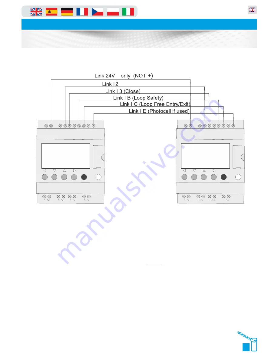
Wiring Diagram
Menu/Ok
SR2 B121BD
1
2
Q1
1
2
Q2
1
2
Q3
1
2
Q4
+
-
I1
I2 I3 I4 IB
ID
IC
IE
24VDC
24VDC
24VDC
Analog or
IB....IE
Inputs I1...I4
Outputs
Q1...Q4 : Relay 8A
Menu/Ok
SR2 B121BD
1
2
Q1
1
2
Q2
1
2
Q3
1
2
Q4
+
-
I1
I2 I3 I4 IB
ID
IC
IE
24VDC
24VDC
24VDC
Analog or
IB....IE
Inputs I1...I4
Outputs
Q1...Q4 : Relay 8A
Master/Slave Wiring
if push buttons
1 safety loop for BOTH barriers
All photo-cells if more than one wired to MASTER barrier only (In series)
(open)
Master/Slave panels are identical, so either barrier can be the master, it just
requires a link between the PLC inputs.
1. Link 24v negative between PLC’s (DO
NOT
LINK + positive)
2. Link I1 between PLC’s - Stop Command
3. Link I2 between PLC’s - Open Command
4. Link I3 between PLC’s - Close Command
5. Link IB between PLC’s - Safety Loop (just needed in master barrier only)
6. Link IC between PLC’s - Free Entry/Exit Loop (Just needed in master
barrier only)
7. Link IE between PLC’s - Photocells (If used if more than one - wire in
series)
Содержание PF6000
Страница 31: ...29 in Parking and access control equipment manufactured in the UK Automatic Raise Arm Barriers Loop Guide ...
Страница 32: ...in Parking and access control equipment manufactured in the UK Automatic Raise Arm Barriers Loop Guide 30 ...
Страница 33: ...31 in Parking and access control equipment manufactured in the UK Automatic Raise Arm Barriers Loop Guide ...
Страница 34: ...in Parking and access control equipment manufactured in the UK Automatic Raise Arm Barriers Loop Guide 32 ...
Страница 35: ...33 in Parking and access control equipment manufactured in the UK Automatic Raise Arm Barriers Loop Guide ...
Страница 36: ...in Parking and access control equipment manufactured in the UK Automatic Raise Arm Barriers Loop Guide 34 ...


