


22
in
Parking and access control equipment manufactured in the UK
Automatic Raise Arm Barriers
Menu/Ok
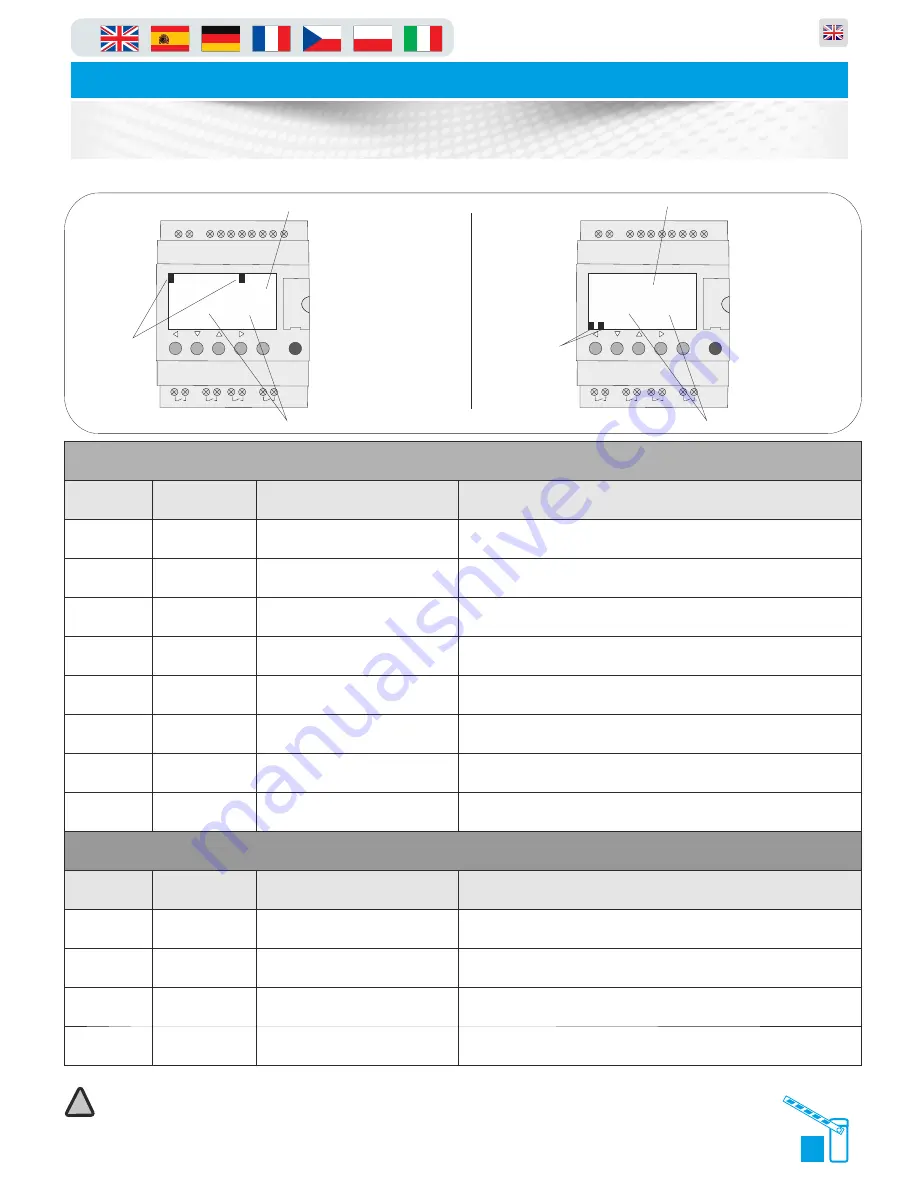
SR2 B121BD
1
2
Q1
1
2
Q2
1
2
Q3
1
2
Q4
+
-
I1
I2 I3 I4 IB
ID
IC
IE
24VDC
24VDC
24VDC
Analog or
IB....IE
Inputs I1...I4
Outputs
Q1...Q4 : Relay 8A
1. Inputs
Input
Polarity
Connected to
Operation when active
I1
Normally Closed
Stop circuit
Barrier stops if door open “Stop Circuit Broken” shown on screen
I2
Normally Open
Raise/Open signal
Barrier is getting a PERMANENT open signal
I3
Normally Open
Lower/Close signal
Lowers barrier
I4
Normally Open
Raise Limit
Barrier arm has reached fully open position. Upper limit switch active
IB
Normally Closed
Loop detector/Safety loop
Detecting vehicle on safety loop. Lowers when vehicle is not detected
IC
Normally Open
Free entry/Free exit loop
Detecting vehicle on free exit/entry loop/ Barrier opens when vehicle present on loop
ID
Normally Open
Lower limit
Arm has reached fully closed position. Lower limit switch active
IE
Normally Closed
Photocells
Photocells Active
2. Outputs
Output:
Polarity:
Connected to:
Operation when active:
Q1
Normally Open
Motor controller open direction
Active to open barrier
Q2
Normally Open
Motor controller close direction
Active to close barrier
Q3
Normally Open
Boom light or Magnetic arm lock
Signal given to accessories
Q4
Normally Open
Flashing beacon/Siren (if installed in
program)
Signal given to accessory if installed in PLC program
The table (bottom) relates to the diagram directly below to help you trouble shoot electrical component errors
Menu/Ok
SR2 B121BD
1
2
Q1
1
2
Q2
1
2
Q3
1
2
Q4
+
-
I1
I2 I3 I4 IB
ID
IC
IE
24VDC
24VDC
24VDC
Analog or
IB....IE
Inputs I1...I4
Outputs
Q1...Q4 : Relay 8A
1.
2.
1
B
234
CDE
RUN LD
SUN 20 JUL
09:36
1234
1234
BCDE
STOP LD
SUN 20 JUL
09:37
1 3
2 4
Input displays
which change
as inputs used
detailed in the
table below.
Example
showing number
I1 and IB input
selected
Showing program in “run mode”
Showing program in “Stop mode”
Output displays
which change
as Outputs used
detailed in the
table below.
Example
showing number
Q1 and Q3
output selected
Date/Time Display
Date/Time Display
Note:
If barriers are set up as a master and slave then see additional wiring info in this section.
!
Содержание PF6000
Страница 31: ...29 in Parking and access control equipment manufactured in the UK Automatic Raise Arm Barriers Loop Guide ...
Страница 32: ...in Parking and access control equipment manufactured in the UK Automatic Raise Arm Barriers Loop Guide 30 ...
Страница 33: ...31 in Parking and access control equipment manufactured in the UK Automatic Raise Arm Barriers Loop Guide ...
Страница 34: ...in Parking and access control equipment manufactured in the UK Automatic Raise Arm Barriers Loop Guide 32 ...
Страница 35: ...33 in Parking and access control equipment manufactured in the UK Automatic Raise Arm Barriers Loop Guide ...
Страница 36: ...in Parking and access control equipment manufactured in the UK Automatic Raise Arm Barriers Loop Guide 34 ...


