Page 4
– Bulletin 100-50-2.1
2. Setup
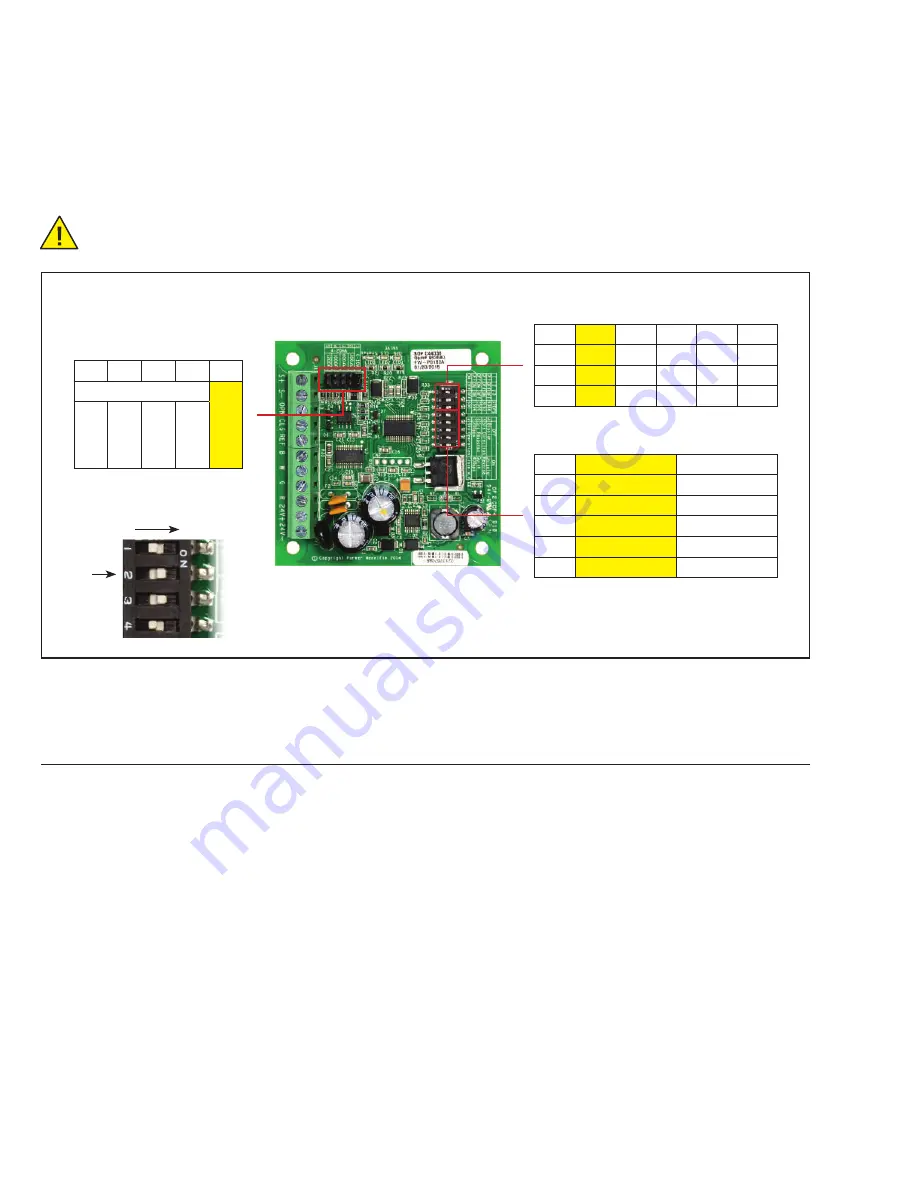
See Figure 2 for locations of input configurations and DIP switches. With the IB-G unpowered, select the input signal of 0-10V
or 4-20mA and desired impedance by installing the supplied jumper to one of the 5 pin locations listed in Table 1. Set the DIP
switches in accordance with the valve and desired operation listed in Table 2 and Table 3. Each DIP switch is considered “OFF”
when the switch is positioned toward the middle of the board. This is the left position in the orientation shown in Figures 2, 2a.
Default settings are highlighted in yellow.
Warning: Do not apply power to the IB-G until setup is complete, and remove power before making any DIP switch
or jumper changes.
Notes:
The selection of “Unipolar” and “1596” steps will override DIP switch #7 to 200 pps.
The selection of “Unipolar” and “500” steps will override DIP switch #7 to 30 pps.
If an invalid valve configuration is set, all 3 LEDs will flash and the valve will not move.
3. System Operation
Normal Valve Operation:
On power-up, the IB-G will initialize by giving the valve a
large number of steps to assure that the valve is fully shut. The
board will not respond to input signals during this time. This
routine will take approximately 30 seconds. After initialization,
the board will position the valve based on the control signal
provided by the external controller. Note: The DIP switches
will override the standard control input. Ensure that the DIP
switches are configured properly. Reference sections below for
further information. The control signal and valve position have
a linear relationship. For example; if the external controller
provides 5VDC signal across terminals ‘S+’ and ‘S-‘ and the
IB-G is set for 0-10V signal, then the valve will be positioned
at 50% open; 7.5VDC signal will position the valve at 75%
open, etc. To allow for component tolerances, the IB-G will
shut the valve when the input signal reaches 4.05 milliamps or
0.05 volts depending on the configuration. If power is lost to
the IB-G or all wires to the valve severed, the valve will remain
in its last position. Solenoid valves may be desired before the
step motor valve on critical applications. The IB-G can power
one or two valves. Two bipolar valves may be used and will
operate simultaneously and will open and close by the same
number of steps. The second valve may be wired into the same
terminals as the first valve. See Appendix C – Wiring Diagram
for details.
Valve force close/open:
If the valve is required to CLOSE during operation, the “CLS”
and “REF” terminals should be used. To close the valve and
pumpdown the system, short terminals “CLS” and “REF”. On
removal of the pumpdown signal the valve will resume position
as dictated by the control signal across “S+” and “S-”.
If the valve is required to OPEN during operation, short
terminals “OPN” and “REF”. This will cause the valve to open
to 100%, once removed the valve will resume normal operation.
Figure 2
Figure 2a
5
4
3
2
1
4-20mA
0-10V
1200
Ω
1000
Ω
600
Ω
300
Ω
Table 1 - Input Signal
(jumper location)
Table 2 – Number of Steps
Table 3 – Valve Type/Operation
DIP # 6386 3196 2500 1596
500
1
OFF
OFF
OFF
OFF
ON
2
OFF
OFF
ON
ON
OFF
3
OFF
ON
OFF
ON
OFF
DIP #
OFF
ON
4
Bipolar
Unipolar
5
Std Direction
Reverse
6
Std Response
Quick
7
200pps
400pps
8
Std Operation
Close Valve
DIP #
ON


