


5.15.4 Interface Mode 04: Analog Control 1
5.15.5 Interface Mode 05: Analog Control 2
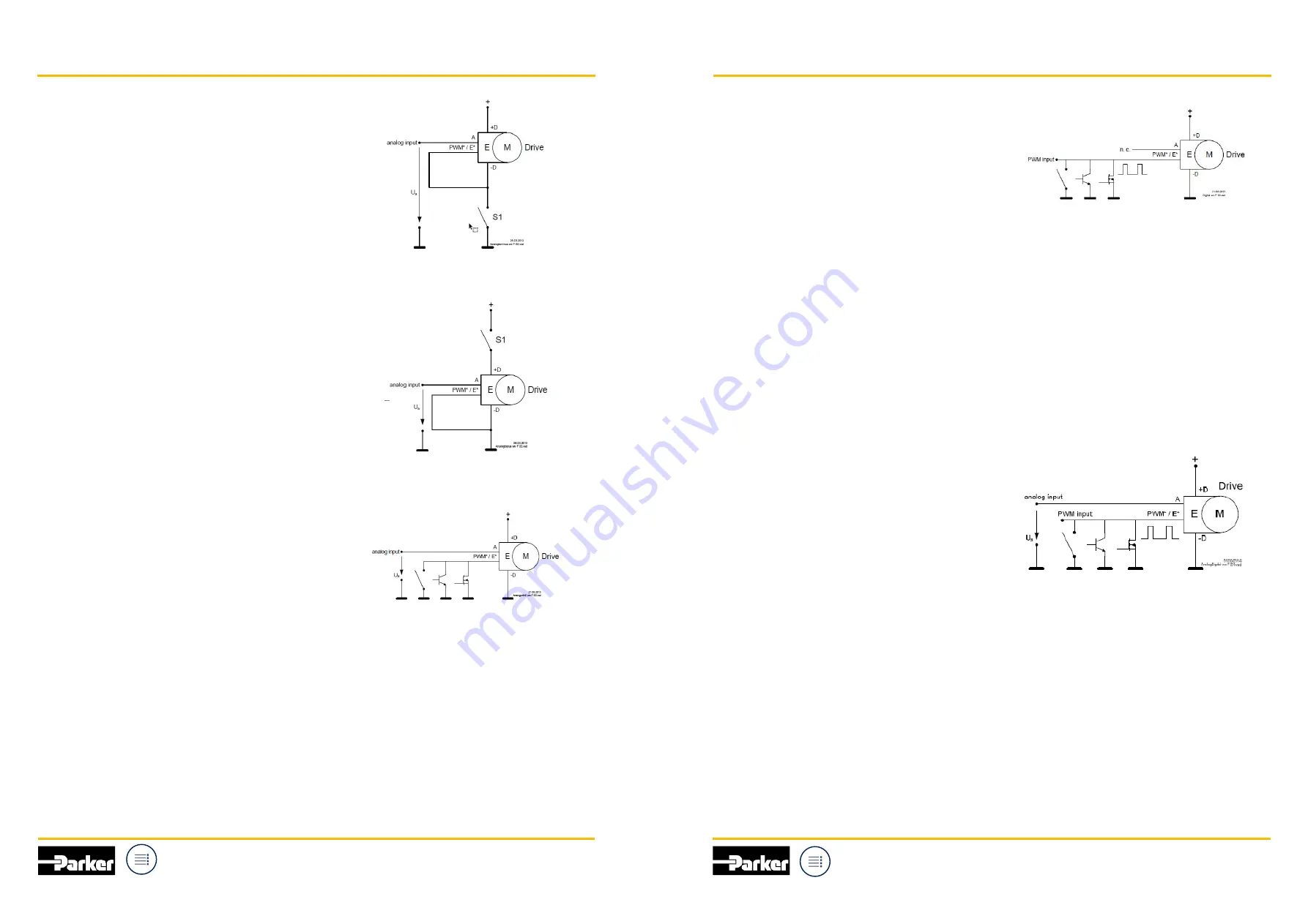
When the switch S1 is switched on the Drive goes after
the initialization of the electronics to the speed
requested by the analog input A.
The appropriate current rating for this “switch” has to
be dimensioned according to the current consumption
of the Drive.
When the switch S1 is switched on the Drive goes after
the initialization of the electronics to the speed
requested by the analog input A.
The appropriate current rating for this “switch” has to
be dimensioned according to the current consumption
of the Drive.
In mode 6 the Drive can stay always on supply voltage
and is controlled by a low current enable input which
can be driven by simple low cost low side signal driver
in the CCU.
When the enable input PWM* / E* goes to high, the
Drive goes after a short time into the quiescent current
mode.
When the enable pin PWM* / E* is driven low, the
Drive goes to the speed requested by the analog input
A after the initialization of the electronics.
The appropriate sink current rating of the driver for the
enable pin PWM* / E* has to be dimensioned
according to the current consumption of the pin
PWM* / E*.
The circuit structure to drive the pin PWM* / E* can be
any active low “open collector”.
In this operating mode the supply voltage plus is
usually connected permanently. To run the Drive first
the pin PWM* / E* has to be connected to supply
voltage minus and afterwards the Drive speed can be
then controlled with an analog voltage on the pin A.
5.15.6 Interface Mode 06: Analog Control with Enable Low
5.15.7 Interface Mode 07: Digital Control
5.15.8 Interface Mode 08: Mixed Analog / Digital Control
In mode 7 the Drive can stay always on supply voltage
and is controlled by a low current PWM and enable
PWM* / E* input which can be driven by simple low
cost low side signal driver in the CCU.
When the enable input PWM* / E* goes to high, the
Drive goes after a short time into the quiescent current
mode.
When the enable pin PWM* / E* is driven with PWM,
the Drive goes to the speed requested by the duty
cycle after the initialization of the electronics.
The appropriate sink current rating of the driver for the
enable pin PWM* / E* has to be dimensioned
according to the current consumption of the pin
PWM* / E*.
The circuit structure to drive the pin PWM* / E* can be
any active low “open collector”.
In this operating mode the supply voltage plus is
usually connected permanently. To run the Drive on
the pin PWM* / E* a PWM signal has to be applied and
with the duty cycle of the PWM signal the Drive speed
can be then controlled.
In mode 8 the Drive can stay always on supply voltage
and is controlled by a low current PWM and enable
PWM* / E* input which can be driven by simple low
cost low side signal driver in the CCU.
When the enable input PWM* / E* goes to high, the
Drive goes after a short time into the quiescent current
mode.
When the enable pin PWM* / E* is driven low (switched
to supply voltage minus), the Drive goes to the speed
requested by the analog input A after the initialization of
the electronics (if the electronics is not already activated).
When the enable pin PWM* / E* is driven with PWM,
the Drive goes to the speed requested by the duty
cycle after the initialization of the electronics (if the
electronics is not already activated).
The appropriate sink current rating of the driver for the
enable pin PWM* / E* has to be dimensioned according
to the current consumption of the pin PWM* / E*.
The circuit structure to drive the pin PWM* / E* can be
any active low “open collector”.
In this operating mode the supply voltage plus is
usually connected permanently. To run the Drive on
the pin PWM* / E* a PWM signal has to be applied and
with the duty cycle of the PWM signal the Drive speed
can be then controlled. If the pin PWM* / E* is switched
to supply voltage minus the Drive speed can be then
controlled with an analog voltage on the pin A.
So a mixed control with either digital or analog input is
possible. The priority has the digital PWM signal.
18
19
Parker Hannifin
Cylinder and Accumulator
Division Europe
Parker Hannifin
Cylinder and Accumulator
Division Europe
Manual and Installation Guide
Manual and Installation Guide
QDC
for electrified mobile applications
QDC
for electrified mobile applications


