OEM750 •
➁
Installation
19
Current Range
Set SW3-#7 and SW3-#8 to select a range for motor current
settings. In
Step 6
of the
Quick Test
you installed a resistor
that determines motor current. Be sure that SW3-#7 and
SW3-#8 are set to the proper current range for the resistor
you installed.
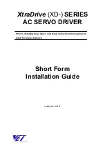
OEM750 Inputs and Outputs
The next figure shows internal connections for the OEM750.
See the following section for OEM750X internal connections.
1
2
14
15
243
Ω
3
2
5
8
6
+5V
464
Ω
5
11
+5V
Step Input
Direction Input
21
9
2
1
16
15
BS170
4N35
Fault Output
23
11
16
17
Remote Input
Gear Shift Input
7
8
681
Ω
10
9
3
4
ILD213
681
Ω
14
13
+5V
10k
Ω
464
Ω
12
243
Ω
HCPL-2631
ILD213
ILD213
ILD213
+5V
464
Ω
+5V
6
Internal Connections
Inputs & Outputs
25 Pin
D-Connector
on OEM750
Inputs and Outputs – OEM750 Schematic
S
TEP
I
NPUT
For every step pulse it receives on its step input, the drive will
commutate the motor to increment rotor position. To send a
step pulse to the drive, apply a positive voltage to
STEP+
with
respect to
STEP–
. The drive registers the pulse on the rising
edge.
The step input is optically isolated. Driving the step input
differentially will provide the best noise immunity. Your input
driver must provide a minimum of 6.5 mA—
approximately 3.5
Содержание OEM750
Страница 64: ... Tuning Specifications OEM750 56 ...
Страница 90: ...EMC INSTALLATION GUIDE OEM750 OEM750X 82 ...
Страница 94: ...INDEX OEM750 86 ...