


IQ-200 User’s Manual
Parker Hannifin Corporation
Hydraulic Filter Division
Metamora, OH
10
Installation and Operation:
To operate the IQ200, the unit needs to be
plumbed on-line and provided a (+)12-24
VDC power supply.
Fluid connections are made through two
SAE-4 (7/16"-20 straight thread with o-ring)
female ports – one at the inlet and one at the
outlet. These ports permit adaptation to a
large variety of fittings. Any fitting that allows
the required flow and does not affect the
fluid’s contamination level is acceptable.
WARNING:
It is necessary that a 1" back-
up wrench be used when making any
connections to the SAE-4 inlet port, to avoid
moving the inlet port fitting.
Any conduit, hose or tube, that provides
adequate flow, can withstand the applied
pressure, and does not affect the fluid’s
contamination level, can be used to
connect the IQ200.
The unit is designed to withstand system
pressures to 3000 PSI (206 BAR), and for
operation, requires a differential pressure
across the unit. The differential pressure
across the unit drives the fluid. The flow
rate, during operation, should be
maintained between 40-60 ml/min, with an
optimum flow rate of 50 ml/min.
Therefore, the required differential
pressure will vary as a result of viscosity
and the condition of the filter element.
It is recommended that a needle valve be
placed downstream of the IQ200 to
maintain backpressure on the unit and
“meter-out” flow.
The IQ200 has an integrated filter, requiring a
specific filter element (PN 935487). It is
necessary to service this filter periodically to
insure the performance of the IQ200. Failure
to maintain the filter element and the integrity
of the seals can affect the performance of the
unit. When servicing the filter, torque the six
3/8"-16 SHCS to 40 ft-lbs.
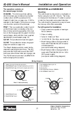
To replace the filter element:
• Remove the six 3/8-16 SHCS using
a 5/16” hex wrench.
• Once the six screws are removed, one
or two of these screws can be screwed
into the auxilliary holes in the cap to
break the seal and provide easy
removal of the cap.
• Once the cap is removed, one screw
can be screwed into the top end cap of
the filter element to lift the element out
of the bowl.
•
WARNING!
Care should be taken not to
drip contaminated fluid from the outside
of the filter element down the element
locator tube.
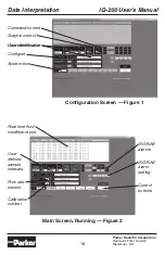
The IQ200 offers both a local display and a
Windows
TM
based software application. Data
acquisition control is provided by an onboard
microcontroller or from a remote location
through the serial port.
Upon startup there is a thirty second window,
where the User can program the IQ200.
During this time the User can select Local or
Remote control, set an Upper and/or Lower
count alarm limit, as well as select the
channel(s) to monitor for the corresponding
alarm(s), set the unit address and activate or
deactivate the RS-485 port. Each time the
unit is powered, the User has the opportunity
to set or revise these settings. Once set, the
unit will maintain all settings whether
powered or not. (see Programming the IQ-
200 and the Local Display)
Installation and Operation
Содержание IQ-200
Страница 1: ...U S E R S M A N U A L IQ 200 On Line Particle Counter...
Страница 2: ......
Страница 30: ...IQ 200 User s Manual Parker Hannifin Corporation Hydraulic Filter Division Metamora OH 30 Notes...
Страница 31: ......