90
– Pvd3665_Gb_Ex_August 2022
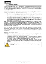
3.7. Thermal Protection
The drive guarantees a 1st level of safety but it is not sufficient. Safety is guaranteed by the
independent relay system described in the connection diagram (§4.3.3) which constitutes
an independent protection circuit meeting safety classification SIL2 in accordance with the
standard IEC 61508.
In the motor, there are two kinds of thermal sensors used for the safety. Both devices are
wired in-series with the coil of the drive power contactor.
•
Two thermoswitches fitted in the servomotor coil mean that the circuit is mechanically
opened on a basis at 125°C±5°C. This protection is reversible, after a decreasing of
the temperature under the basis, the circuit is mechanically closed.
•
A thermofuse fitted with a contact on the servomotor frame means that the circuit is
mechanically opened on a permanent basis at 130°C-5°C. In case of an over
temperature and thermoswitches default, the thermo fuse cuts off permanently the
power supply to the contactor coil.
Both thermoswitches and thermofuse are wired in-series with the coil of the drive power
contactor. If the maximum temperature is reached, the thermoswitches are opened and
temporarily cut off the power supply to the contactor coil. If the temperature reaches a
dangerous level (thermoswitches default), the thermofuse melts; permanently cutting off the
power supply to the contactor coil.
The drive can be equipped with a Safe Torque Off function in accordance with EN
ISO13849-1 : 2006 and EN 61800-5-2:2006 and validated by a notified organization. In this
case the safety system can be connected to this function with a validation of a notified
organization.
Caution :
(see diagrams §4.3.3) :
•
Make sure the parameters of the contactor and the connecting are strictly followed.
•
The motor is out of order if the thermofuse is activated!
•
The power contactor KM1 should be replaced in accordance with its operation
lifespan and number of manoeuvres. A yearly test, intended to check on the ability of
the contactor to detect condition changes, should also be carried out.
•
The thermal sensors, due to their thermal inertia, are unable to follow very fast
winding temperature variations. They acheive their thermal steady state after a few
minutes.
Warning: To protect correctly the motor against very fast overload, please
refer to 3.1.6. Peak current limitations
Содержание EX Series
Страница 1: ...1 Pvd3665_Gb_Ex_August 2022 Servomotors EX Series Technical Manual PVD 3665 EX...
Страница 2: ...2 Pvd3665_Gb_Ex_August 2022...
Страница 3: ...3 Pvd3665_Gb_Ex_August 2022...
Страница 4: ...4 Pvd3665_Gb_Ex_August 2022...
Страница 5: ...5 Pvd3665_Gb_Ex_August 2022...
Страница 6: ...6 Pvd3665_Gb_Ex_August 2022...
Страница 7: ...7 Pvd3665_Gb_Ex_August 2022...
Страница 8: ...8 Pvd3665_Gb_Ex_August 2022...
Страница 9: ...9 Pvd3665_Gb_Ex_August 2022...
Страница 10: ...10 Pvd3665_Gb_Ex_August 2022...
Страница 11: ...11 Pvd3665_Gb_Ex_August 2022...
Страница 12: ...12 Pvd3665_Gb_Ex_August 2022...
Страница 13: ...13 Pvd3665_Gb_Ex_August 2022...
Страница 14: ...14 Pvd3665_Gb_Ex_August 2022...
Страница 15: ...15 Pvd3665_Gb_Ex_August 2022...
Страница 16: ...16 Pvd3665_Gb_Ex_August 2022...
Страница 17: ...17 Pvd3665_Gb_Ex_August 2022...
Страница 18: ...18 Pvd3665_Gb_Ex_August 2022...
Страница 19: ...19 Pvd3665_Gb_Ex_August 2022 Compliance with UL standards...
Страница 20: ...20 Pvd3665_Gb_Ex_August 2022 Compliance with UL standards...
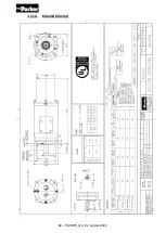
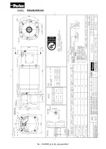
Страница 73: ...73 Pvd3665_Gb_Ex_August 2022 3 3 Dimension drawings 3 3 1 EX310E...
Страница 74: ...74 Pvd3665_Gb_Ex_August 2022 3 3 2 EX420E EX430E...
Страница 75: ...75 Pvd3665_Gb_Ex_August 2022 3 3 3 EX620E EX630E...
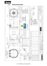
Страница 76: ...76 Pvd3665_Gb_Ex_August 2022 3 3 4 EX820E EX840E EX860E...
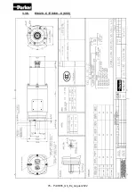
Страница 77: ...77 Pvd3665_Gb_Ex_August 2022 3 3 5 EX310 C CCC...
Страница 78: ...78 Pvd3665_Gb_Ex_August 2022 3 3 6 EX420 C EX430 C CCC...
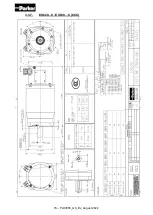
Страница 79: ...79 Pvd3665_Gb_Ex_August 2022 3 3 7 EX620 C EX630 C CCC...
Страница 80: ...80 Pvd3665_Gb_Ex_August 2022 3 3 8 EX820 C EX820 C EX820 C CCC...
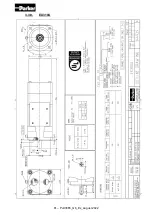
Страница 81: ...81 Pvd3665_Gb_Ex_August 2022 3 3 9 EX310U...
Страница 82: ...82 Pvd3665_Gb_Ex_August 2022 3 3 10 EX420U EX430U...
Страница 83: ...83 Pvd3665_Gb_Ex_August 2022 3 3 11 EX620U EX630U...
Страница 84: ...84 Pvd3665_Gb_Ex_August 2022 3 3 12 EX820U EX840U EX860U...
Страница 93: ...93 Pvd3665_Gb_Ex_August 2022 3 8 5 Mains supply connection diagrams 3 8 5 1 EX310E...
Страница 94: ...94 Pvd3665_Gb_Ex_August 2022 3 8 5 2 EX420E EX430E...
Страница 95: ...95 Pvd3665_Gb_Ex_August 2022 3 8 5 3 EX620E EX630E...
Страница 96: ...96 Pvd3665_Gb_Ex_August 2022 3 8 5 4 EX820E EX840E EX860E...
Страница 97: ...97 Pvd3665_Gb_Ex_August 2022 3 8 5 5 EX310 C CCC...
Страница 98: ...98 Pvd3665_Gb_Ex_August 2022 3 8 5 6 EX420 C EX430 C CCC...
Страница 99: ...99 Pvd3665_Gb_Ex_August 2022 3 8 5 7 EX620 C EX630 C CCC...
Страница 100: ...100 Pvd3665_Gb_Ex_August 2022 3 8 5 8 EX820 C EX840 C EX860 C CCC...
Страница 101: ...101 Pvd3665_Gb_Ex_August 2022 3 8 5 9 EX310U...
Страница 102: ...102 Pvd3665_Gb_Ex_August 2022 3 8 5 10 EX420U EX430U...
Страница 103: ...103 Pvd3665_Gb_Ex_August 2022 3 8 5 11 EX620U EX630U...
Страница 104: ...104 Pvd3665_Gb_Ex_August 2022 3 8 5 12 EX820U EX840U EX860U...
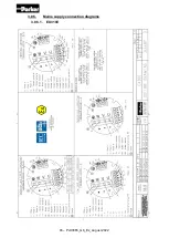
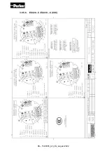
Страница 126: ...126 Pvd3665_Gb_Ex_August 2022 4 3 3 Connection diagrams 4 3 3 1 EX3 EX4 DC supply 4 3 3 2 EX single phase...
Страница 128: ...128 Pvd3665_Gb_Ex_August 2022 4 3 4 Cable glands informations Only ATEX IECEx 4 3 4 1 Technical data...

