


12
Parker Hannifin Corporation • Refrigerating Specialties Division
2445 South 25th Avenue • Broadview, IL 60155-3891
Telephone: (708) 681-6300 • Fax (708) 681-6306
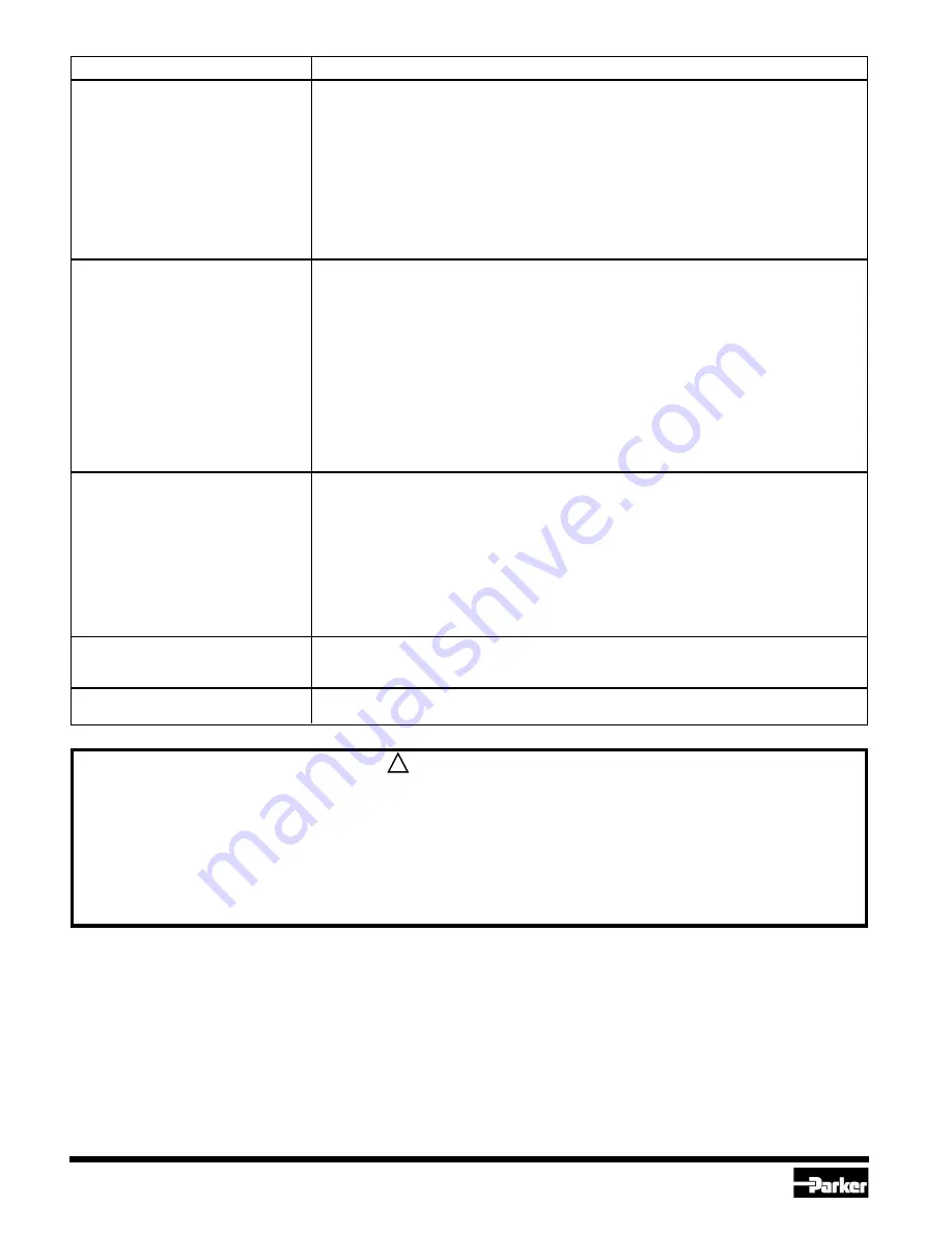
Recommended Trouble-Shooting Procedure
1. Check TB3 for voltage across teminals 1 and 3. If no voltage, check source of power to
determine why.
2. If 110V/50Hz or 120V/60Hz then shunt plug should be positioned to reveal "120 VAC". If
"240 VAC" is revealed then the shunt plug is in the wrong position and must be changed to
reveal "120 VAC". Disconnect power before making this change.
3. If 220V/50Hz or 240V/60Hz then shunt plug should be positioned to reveal "240 VAC".
If "120 VAC" is revealed then the shunt plug is in the wrong position and the Printed Circuit
Board may have been destroyed and may have to be replaced.
4. Check transformer operation with a DC voltmeter on T131 across terminals 2 and 3
(common) to be positive 15 volts, and across terminals 4 and 3 (common) to be negative
15 volts.
1. Check voltage on TB1 across terminals 1 and 3 (common) to be between 0 and 1 volt DC
and should be proportional to the liquid level.
2. Pipe Column is not properly insulated and liquid refrigerant is boiling, indicating a false
high level.
3. Liquid refrigerant in the Pipe Column contains too much oil. The indication will be a false
low level. If an Ammonia system, the oil will be near the bottom and can be drained off.
If a Halocarbon system, the oil-rich mixture will be near the top of the Pipe Column and
this indicates a basic problem with the system, not the ELL.
4. An excessive and continuously high LED display could mean there is a fault in the PTFE
enclosure around the Probe, allowing the refrigerant to penetrate to a direct contact with
the steel rod.
5. If "240 VAC" is revealed on the shunt plug and the voltage across terminals 1 and 3 of TB3
is 120 VAC the probe will read about half of its actual reading.
1. Check to see that all electrical connections are tight. Disconnect power to Controller
before this is done.
2. The ELL may be displaying factual information and the liquid level is for some reason
surging or changing level on an erratic basis. Check to see that the hand shut-off valves in
the equalizing lines are fully open. Check for dirt and/or oil in the Pipe Column and
equalizing lines. Is Pipe Column adequately sized?
For most applications, we recommend 3" or 4" (75 or 100 mm) pipe size.
3. The Probe Assembly must have a mechanically and an electrically sound connection to
the Pipe Column. Disconnect power and check to see that both conditions exist.
4. Fault in PTFE enclosure around Probe.
The "Zero" calibration process must be rechecked. The Pipe Column must be empty of liquid
and the "Zero" adjusting screw turned so that the LED Bar Graph display reads very close to
zero AND a (-) sign is not at the left of the LED Digital display.
The chip that converts the incoming voltage to a signal for the Bar Graph has malfunctioned.
Replace Display Board Assembly, part number 203393.
Safe Operation (See Also Bulletin RSB)
People doing any work on a refrigeration system must be qualified
and completely familiar with the system and the Refrigerating
Specialties Division Products involved, or all other precautions will be
meaningless. This includes reading and understanding pertinent
Refrigerating Specialties Division Product Bulletins and Safety Bulletin
RSB prior to installation or servicing work.
Where cold refrigerant lines are used, it is necessary that certain
precautions be taken to avoid damage which could result from liquid
expansion. Temperature increase in a piping section full of solid liquid
will cause high pressure due to expanding liquid which can possibly
rupture a gasket, pipe or valve. All hand valves isolating such sections
should be marked, warning against accidental closing, and must not
This document and other information from Parker Hannifin Corporation, its subsidiaries and authorized distributors provide product and/or system options for
further investigation by users having technical expertise. It is important that you analyze all aspects of your application and review the information concerning
the product or system in the current product catalog. Due to the variety of operating conditions and applications for these products or systems, the user,
through its own analysis and testing, is solely responsible for making the final selection of the products and systems and assuring that all performance, safety
and warning requirements of the application are met.
The products described herein, including without limitation, product features, specifications, designs, availability and pricing, are subject to change by Parker
Hannifin Corporation and it subsidiaries at any time without notice.
be closed until the liquid is removed. Check valves must never be
installed upstream of solenoid valves, or regulators with electric
shut-off, nor should hand valves upstream of solenoid valve or
downstream of check valves be closed until the liquid has been
removed. It is advisable to properly install relief devices in any section
where liquid expansion could take place.
Avoid all piping or control arrangements which might produce thermal
or pressure shock.
For the protection of people and products, all refrigerant must be
removed from the section to be worked on before a valve, strainer or
other device is to be opened or removed.
WARNING
FAILURE OR IMPROPER SELECTION OR IMPROPER USE OF THE PRODUCTS AND/OR SYSTEMS DESCRIBED HEREIN OR
RELATED ITEMS CAN CAUSE DEATH, PERSONAL INJURY AND PROPERTY DAMAGE.
!
Problem
LED’s not working
Probe is not registering
the proper level
LED has erratic operation
The Digital/Bar Graph LED
moves in the wrong direction
when the liquid is changing.
Bar Graph does not match
Digital Display reading.
Содержание ELL-1
Страница 3: ...Refrigerating Specialties Division 3...
Страница 6: ...Refrigerating Specialties Division 6...
Страница 8: ...Refrigerating Specialties Division 8 Electronic Liquid Level Kits 204643...
Страница 10: ...Refrigerating Specialties Division 10...


