Chapter 2 – Installation
35
E-DC Hardware Installation Guide
7 – C
ONNECT
THE
M
OTOR
TO
THE
L
OAD
– C
OUPLERS
Align the motor shaft and load as accurately as possible. In most applica-
tions, some misalignment is unavoidable, due to tolerance buildups in
components. However, excessive misalignment may degrade your system’s
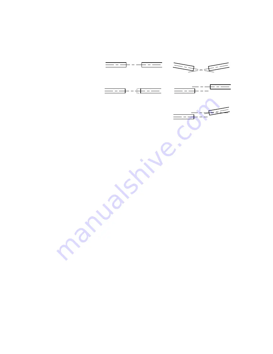
performance. The three misalignment conditions, which can exist in any
combination, are illustrated and described below.
Aligned
Parallel Misalignment
Combined Parallel & Angular Misalignment
End Float
Angular Misalignment
Misalignment Condition
•
Angular Misalignment: The center lines of two shafts intersect at an angle
other than zero degrees.
•
Parallel Misalignment: The offset of two mating shaft center lines, although
the center lines remain parallel to each other.
•
End Float: A change in the relative distance between the ends of two shafts.
The type of misalignment in your system will affect your choice of coupler.
S
INGLE
-F
LEX
C
OUPLING
Use a single-flex coupling when you have angular misalignment only.
Because a single-flex coupling is like a hinge, one and only one of the
shafts must be free to move in the radial direction without constraint.
Do
not use a double-flex coupling in this situation
: it will allow too much
freedom and the shaft will rotate eccentrically, which will cause large
vibrations and catastrophic failure.
Do not use a single-flex coupling with a
parallel misalignment
: this will bend the shafts, causing excessive bearing
loads and premature failure.
D
OUBLE
-F
LEX
C
OUPLING
Use a double-flex coupling whenever two shafts are joined with parallel
misalignment, or a combination of angular and parallel misalignment (the
most common situation).
Single-flex and double-flex couplings may or may not accept end play,
depending on their design.
R
IGID
C
OUPLING
Rigid couplings are generally not recommended, because they cannot
compensate for
any
misalignment. They should be used only if the motor
or load is on some form of floating mounts that allow for alignment com-
pensation. Rigid couplings can also be used when the load is supported
entirely by the motor’s bearings. A small mirror connected to a motor
shaft is an example of such an application.
C
OUPLING
M
ANUFACTURERS
HUCO
ROCOM CORP.
HELI-CAL
70 Mitchell Blvd, Suite 201 5957 Engineer Drive
P.O. Box1069
San Rafael, CA 94903
Huntington Beach, CA 92649 Santa Maria, CA 93456
(415) 492-0278
(714) 891-9922
(805) 928-3851
www.comoso.com
Содержание E-DC
Страница 4: ...4 E DC Hardware Installation Guide www comoso com...
Страница 8: ...8 E DC Hardware Installation Guide Chapter 1 Introduction www comoso com...
Страница 46: ...46 E DC Hardware Installation Guide Chapter 3 Troubleshooting www comoso com...
Страница 50: ...50 E DC Hardware Installation Guide Appendix A LVD Installation Instructions www comoso com...
Страница 60: ...60 E DC Hardware Installation Guide Appendix B EMC Installation Guide www comoso com...


