Parker DUSTHOG PNP Скачать руководство пользователя страница 16

12

DUSTHOG PNP Series

3.4.1 Electrical Supply Power

The main power supply is connected to the PNP unit through a 1˝ FNPT coupling located on the rear 
of the unit shown in Figure 1B. After feeding wires through the coupling, terminations are made on 
the main bus bar terminal for each phase and frame ground connection. The rear electrical panel also 
contains the unit circuit breakers and DC power supply for the controls components. Utilize Table 1 
for wire, fuse and disconnect sizing for your respective product model. A second plugged 1˝ FNPT 
coupling is also located on the rear of the cabinet for low optional voltage connections using the 
process control feature to automate operation. Ensure that the rear electrical panel cover is in place 
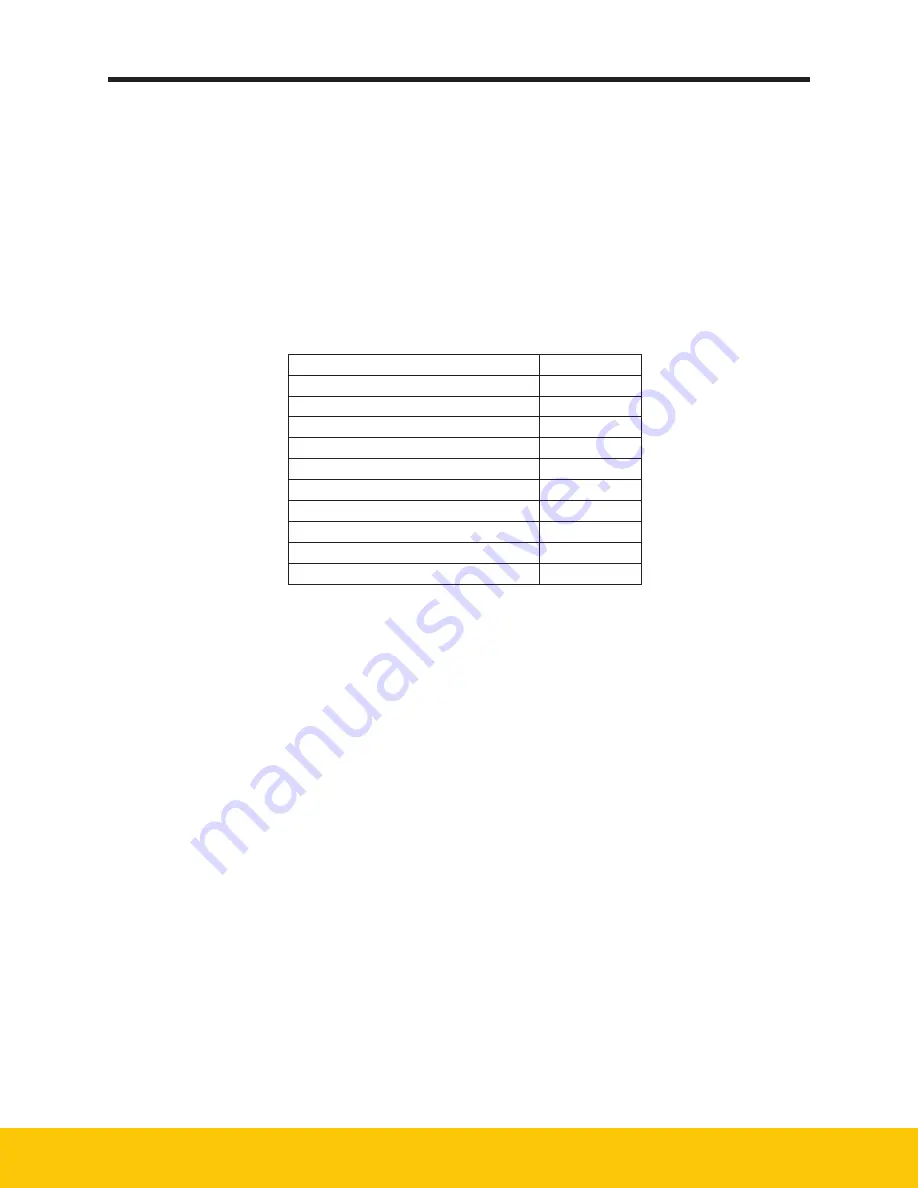
and secured prior to operating the unit. Refer to the electrical wiring diagrams in Table 2 for additional 
wiring information. 

Note:

 When making the main power connections to the unit, fan rotation check is not required.  

The blower will automatically turn in the correct direction.

Descripon of Wire Diagram 

Appendix

Transformer 575:480 

A1

One Blower & Controls 

A2

Two Blower & Controls 

A3

Three Blower & Controls 

A4

Four Blower & Controls 

A5

Remote Panel Controls 

A6

One Blower & Remote Controls 

A7

Two Blower & Remote Controls 

A8

Three Blower & Remote Controls 

A9

Four Blower & Remote Controls 

A10

TABLE 2

Wire Diagrams

3.4.2  Electrical Touchscreen Controls

The main control panel for the PNP unit is a touchscreen interface located integrally on the front of 
the unit or remotely in an auxiliary enclosure (refer to section 3.4.3) that operates the blower and filter 
pulse cleaning system. Both the touchscreen control panel and filter pulse cleaning valves are powered 
by 24V DC. Refer to Section 4 of this manual for operation of the touchscreen. All wiring in the 
touchscreen controls panel is pre-wired at the factory and there are no customer connections at this 
panel. The panel door should remain closed and locked during operation.

3.4.3 Remote Controls Panel

The PNP unit is available with a remote controls panel that allows touchscreen controls to be located 
within 100 ft. (30.5 m) from the PNP unit location. The controls are provided in a NEMA 4X enclosure 
for mounting. The remote display panel will come pre-wired with two cables, one is the 24 VDC power 
supply, along with control cables and the other is a communications cable that must be connected 
to the PNP unit upon installation. Note that these wires are low voltage and should not be run next to 
high voltage wires. These wires should be cut to final length at installation.

Содержание DUSTHOG PNP

Страница 1: ...DUSTHOG Plug Play Fume Dust Collector Owner s Manual Model PNP...

Страница 2: ...ave the following information available when contacting Parker Unit Order ___________________________________________________________________ Unit Model _______________________________________________...

Страница 3: ...ical Touchscreen Controls 10 Remote Controls Panel 10 Process Control 11 Step Down Transformer Package 11 4 0 Unit Operation 11 4 1 Start up 11 4 2 System Operation 12 Airflow Adjustment Using Manual...

Страница 4: ...Keep flammable materials and vapors such as gasoline away from unit The unit should be inspected frequently and contaminants removed to prevent excessive accumulation which may result in flash over or...

Страница 5: ...ims any liability or responsibility for damage from fires or explosions regardless of origin Parker recommends that all APC dust collection equipment installation and application conform to any and al...

Страница 6: ...Page intentionally left blank...

Страница 7: ...st collection please do not hesitate to call your local Parker representative 2 1 DUSTHOG Nomenclature DUSTHOG air filtration systems are available in a variety of configurations and sizes Codes shown...

Страница 8: ...tronics are housed in this cabinet The compressed air supply connection is located on the rear of the cabinet The system control panel is located at the front of the module on a tool operated hinged a...

Страница 9: ...5 DUSTHOG PNP Series Figure 1B PNP Equipment Description 61 10120 Figure 1A PNP Equipment Description...

Страница 10: ...the shipper at once so that damages and or shortages can be corrected and a claim can be filed without delay TIP OVER HAZARD Lift the PNP unit and components by the packing skids or on the lifting ey...

Страница 11: ...7 DUSTHOG PNP Series 61 10121 Figure 2 PNP Weights and Lifting Info...

Страница 12: ...ressed air line To ensure a liquid free compressed air supply Parker recommends installing a point of use coalescing filter with an automatic drain port prior to the unit Consult your local Parker rep...

Страница 13: ...een purchased with an optional drawer liner If this is the case ensure that the bag and hold down bracket is installed correctly and is secured to the drawer The bag should be set in the drawer and sp...

Страница 14: ...e filter should be compressed by 30 50 A center bracket is also supplied that runs in the same direction it is placed immediately over the seam where the two filters are butted together Reference ball...

Страница 15: ...11 DUSTHOG PNP Series 61 10122 Figure 4B After Filter Removal and Installation Figure 4A PNP Primary Filter Removal Installation...

Страница 16: ...Panel Controls A6 One Blower Remote Controls A7 Two Blower Remote Controls A8 Three Blower Remote Controls A9 Four Blower Remote Controls A10 TABLE 2 Wire Diagrams 3 4 2 Electrical Touchscreen Control...

Страница 17: ...the PNP filter access doors and verify that the filters are in place and properly sealed 2 Open the dust drawer access door and verify that the dust drawer is in place 3 Close and latch all access doo...

Страница 18: ...he airflow set point When the system can no longer maintain airflow a warning will be provided on the touchscreen In the event of a warning or failure on the touchscreen refer to the troubleshooting s...

Страница 19: ...en When you want to use the unit just tap the screen with your finger and it will change to the main display screen shown in Figure 6 The home display screen shown in Figure 6 will be displayed during...

Страница 20: ...a change of 1 This will increase or decrease the airflow adjustment by 1 for each touch of the up or down arrows The second method of airflow adjustment is to touch the box that shows the percentage...

Страница 21: ...3 6 Customer Settings The standard customer settings screen shown in Figure 13 will allow the operator to make General Setting changes without a password The Locked Settings will require a password t...

Страница 22: ...long as the blower is in operation The last mode is Down Time cleaning This cleaning mode can be used in conjunction with all previous modes The selection of this mode is for cleaning the filters aft...

Страница 23: ...lected at order time and loaded into the PNP at the factory The Auto Flow Settings will allow the unit to maintain a precise operating point based on a desired air volume The operator will select an a...

Страница 24: ...g or replacing filter elements Dust accumulated on the filter elements can result in irritation of the lungs skin and or eyes When the primary filters reach the point of not being able to maintain pro...

Страница 25: ...ing handle is mounted on the bottom side of the bin which should be slid outward and can pivoted upward for a more ergonomic and convenient removal of the bin from the dust drawer 5 Once removed from...

Страница 26: ...clean no leaks Screen Displayed Warning Possible Causes Recommended Solu ons Filter Cau on Filters approaching end of life Replace filter s soon ensure proper pulse cleaning opera on increase down me...

Страница 27: ...23 DUSTHOG PNP Series Page intentionally left blank...

Страница 28: ...3 m 5 33 10082 0002 AFTER FILTER HEPA 99 97 0 3 m 6 39 10008 0006 CONTROLS PANEL LATCH 10mm HEX 7 39 10058 FLUSH MOUNT FILTER CABINET LATCH 8 39 10059 FLUSH MOUNT MOTOR CABINET LATCH TOOL OPERATED 11...

Страница 29: ...25 DUSTHOG PNP Series PNP 12 Figure 24 PNP Replacement Parts 61 10123...

Страница 30: ...26 DUSTHOG PNP Series A1 Transformer 575 480 8 Appendix Wiring Diagrams 04 001886...

Страница 31: ...27 DUSTHOG PNP Series A2 One Blower Controls 04 001830...

Страница 32: ...28 DUSTHOG PNP Series A3 Two Blower Controls 04 001831...

Страница 33: ...29 DUSTHOG PNP Series A4 Three Blower Controls 04 001832...

Страница 34: ...30 DUSTHOG PNP Series A5 Four Blower Controls 04 001881...

Страница 35: ...31 DUSTHOG PNP Series A6 Remote Panel Controls 04 001868...

Страница 36: ...32 DUSTHOG PNP Series A7 One Blower Remote Controls 04 001833 A7...

Страница 37: ...33 DUSTHOG PNP Series A8 A8 Two Blower Remote Controls 04 001834...

Страница 38: ...34 DUSTHOG PNP Series A9 Three Blower Remote Controls 04 001863...

Страница 39: ...35 DUSTHOG PNP Series A10 Four Blower Remote Controls 04 001864...

Страница 40: ...ormal use or misuse misapplication or normal wear and tear e Equipment not properly installed operated and maintained under normal conditions and recommended applications As Buyers exclusive remedy fo...

Страница 41: ...f troubleshooting effort details 5 Description of physical location and or environment details The Buyer shall cooperate with PARKER in its investigation and provide full information and documentation...

Страница 42: ...tten Leur Netherlands 31 76 508 5300 www parker com dhfns Hiross Zander Essen Germany 49 2054 9340 www parker com hzfd Padova Italy 39 049 9712 111 www parker com hzfd Engine Filtration Water Purifica...

Отзывы: