➁
Installation
37
Gain Reduction
Control Circuit
Error
Signal
from DAC
KP
(fixed)
KI
RI
KD
Torque
Command
Derivative
Gain
Reduction
(5 D-GAIN RED)
Proportional
Gain Adjust
Loop Gain
Integral
Gain Adjust
Derivative
Gain Adjust
Integral
Gain
Disable
(6 I-GAIN OFF)
Σ
+
+
+
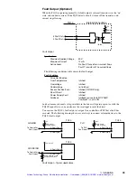
PID Control Loop – Block Diagram
You can adjust three potentiometers to tune the PID loop. These potentiometers control the
settings for proportional gain, integral gain, and derivative gain. You can also make two
other adjustments: you can connect the terminal labeled
D-GAIN RED
to ground, to reduce
derivative gain; and you can connect the terminal labeled
I-GAIN OFF
to ground, to disable
integral gain.
These five tuning parameters are described in the next sections.
Proportional Gain
Proportional gain provides a torque that is directly proportional to the
magnitude
of the
error signal. Proportional gain is similar to a spring—the larger the error, the larger the
restoring force. It determines the stiffness of the system and affects the following error.
High proportional gain gives a stiff, responsive system, but can result in overshoot and
oscillation. Damping—provided by derivative gain—can reduce this overshoot and
oscillation.
Notice from the block diagram that adjusting proportional gain affects the loop gain. This
means that integral gain and derivative gain are both affected by changes in the propor-
tional gain tuning potentiometer. This arrangement simplifies tuning; once you set the
integral and derivative gains in the correct ratio to proportional gain, you only need to
adjust proportional gain—integral and derivative gain will follow.
Derivative Gain
Derivative gain provides a torque that is directly proportional to the
rate of change
of the
error signal. When the error’s instantaneous rate of change, or
derivative
, increases,
derivative gain also increases. Derivative gain opposes rapid changes in velocity. It will
dampen the resonance effects of proportional gain. With higher derivative gain, you can use
higher proportional gain.
Derivative Gain Reduction
Many applications require high derivative gain for proper performance. High derivative
gain, however, can cause jitter and audible noise at the shaft when the motor is at rest.
Many applications have enough “stiction” so that high derivative gain is not necessary for
stability when the system is at rest. If your application must hold position with minimum
jitter or noise, connect a wire from the terminal labeled
D-GAIN RED
to ground (see the
Inputs and Outputs
section earlier in this chapter). With this terminal grounded, the drive
will gradually reduce derivative gain to a low value whenever motion stops. When motion
starts again, or if the motor shaft moves, the drive will instantly increase derivative gain to
the value set by the tuning potentiometer.
Artisan Technology Group - Quality Instrumentation ... Guaranteed | (888) 88-SOURCE | www.artisantg.com


