


20
TQ10 User Guide
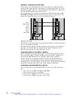
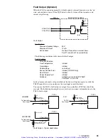
Connecting Compumotor SM or NeoMetric Series Motors
To connect a Compumotor SM or NeoMetric Series servo motor to the TQ10, follow the
color code shown in the next drawing.
Red/Yellow
White/Yellow
Black/Yellow
Green/Yellow
Phase A
Phase B
Phase C
Motor Ground
Shield "Drain" wire
Shield "Drain" wire
No insulation
No insulation
White/Green
White/Blue
White/Brown
White/Orange
White/Violet*
Yellow
Yellow
*
White/Yellow
on some
cables
4
5
6
7
8
9
10
Hall Gnd
Hall +5V
Hall 1
Hall 2
Hall 3
Motor Temp +
Motor Temp -
"Thick" Wires: (including Motor Temp
±
)
SM 16x: 20 AWG (0.5 mm2)
SM 23x: 16 AWG (1.5 mm2)
"Thin" Wires (Hall 1, 2, 3, +5V, Gnd):
24 AWG (0.25 mm2)
Encoder
Cable
SM or NeoMetric
Motor with
TQ Cable
Motor Cable
Do not extend wires more than
2" (50 mm) beyond cable shield
12
Motor Cable Connections for SM and NeoMetric Series Motors
Inside the motor cable, there are two sets of wires. One contains Hall effect and motor
thermostat wires; the other contains motor phase wires. Each set of wires has its own shield
and shield drain wire. As shown in the drawing, you should connect both drain wires and
the green/yellow ground wire to the
MOTOR GROUND
connector.
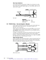
Optional – Connect an External Regeneration Resistor
The TQ10 Drive can dissipate regenerated energy in its internal
regeneration resistor
. If
your system regenerates more energy than the internal resistor can dissipate, you can
connect an external resistor between two terminals called
V Bus+
and
Regen Resistor
,
located on the motor connector. The external resistor doubles the TQ10’s dissipation
capabilities.
WARNING
Potentially hazardous voltages are present on
V Bus+
and
Regen Resistor
terminals when
power is applied to the drive.
Artisan Technology Group - Quality Instrumentation ... Guaranteed | (888) 88-SOURCE | www.artisantg.com