Chapter 4: Infrared Object Detection · Page 41
SUMOBOT MOTION CONTROL
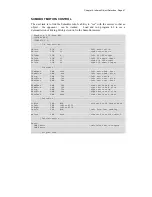
The next task is to link the SumoBot robot’s ability to "see" with the motors so that an
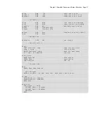
object – the opponent – can be tracked. Load and run program 4.2 to see a
demonstration of linking IR object control to the SumoBot motors.
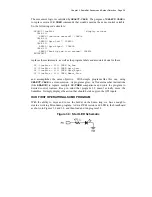
' SumoBot_4.2_IR_Scan.BS2
' {$STAMP BS2}
' {$PBASIC 2.5}
' -----[ I/O Definitions ]-------------------------------------------------
LMotor PIN 13 ' left servo motor
RMotor PIN 12 ' right servo motor
LfIrOut PIN 4 ' left IR LED output
LfIrIn PIN 11 ' left IR sensor input
RtIrOut PIN 15 ' right IR LED output
RtIrIn PIN 14 ' right IR sensor input
' -----[ Constants ]-------------------------------------------------------
LFwdFast CON 1000 ' left motor fwd; fast
LFwdSlow CON 800 ' left motor fwd; slow
LStop CON 750 ' left motor stop
LRevSlow CON 700 ' left motor rev; slow
LRevFast CON 500 ' left motor rev; fast
RFwdFast CON 500 ' right motor fwd; fast
RFwdSlow CON 700 ' right motor fwd; slow
RStop CON 750 ' right motor stop
RRevSlow CON 800 ' right motor rev; slow
RRevFast CON 1000 ' right motor rev; fast
' -----[ Variables ]-------------------------------------------------------
irBits VAR Nib ' storage for IR target data
irLeft VAR irBits.BIT1
irRight VAR irBits.BIT0
lastIr VAR Nib ' info from last reading
pulses VAR Byte ' counter for motor control
' -----[ Initialization ]--------------------------------------------------
Reset:
LOW LMotor ' initialize motor outputs
LOW RMotor
' -----[ Program Code ]----------------------------------------------------
Содержание Boe-Bot
Страница 1: ...SumoBot Mini Sumo Robotics Assembly Documentation and Programming VERSION 2 1...
Страница 4: ......
Страница 9: ...Preface Page ix...
Страница 10: ......
Страница 20: ......
Страница 32: ......
Страница 54: ......
Страница 74: ......
Страница 76: ......
Страница 77: ...Appendix D SumoBot PCB Schematic Page 67 Appendix D SumoBot PCB Schematic...


