Chapter 3: SumoBot Sensors and Border Detection · Page 25
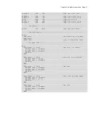
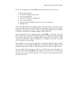
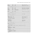
Read_Left:
HIGH LLinePwr ' activate sensor
HIGH LLineIn ' discharge QTI cap
PAUSE 1
RCTIME LLineIn, 1, lLine ' read sensor value
LOW LLinePwr ' deactivate sensor
RETURN
Read_Right:
HIGH RLinePwr ' activate sensor
HIGH RLineIn ' discharge QTI cap
PAUSE 1
RCTIME RLineIn, 1, rLine ' read sensor value
LOW RLinePwr ' deactivate sensor
RETURN
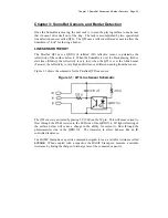
HOW IT WORKS
This program starts by activating the left QTI line sensor, then bringing its R line high to
discharge the onboard capacitor (both sides of the capacitor will be at 5v, hence it is
discharged). A one millisecond
PAUSE
gives the capacitor plenty of time to discharge
through the 220
Ω
resistor.
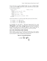
After the capacitor is fully discharged,
RCTIME
makes the R line an input and allows the
capacitor to begin to charge (the plate connected to the R line will move toward Vss).
While the capacitor is charging, the
RCTIME
instruction increments an internal counter.
When the BASIC Stamp sees approximately 1.4 volts on the R line, the counter value is
placed in the output variable called
lLine
. At this point the process is complete and the
QTI is deactivated.
The process is repeated for the right-side QTI and
DEBUG
is used to display the values.
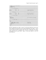
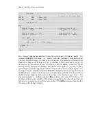
Figure 3.2 shows the output of the program with the left QTI over the Tawara (white
border) line and the right QTI over the black playing field. Notice the dramatic
difference between the two values.
Run the program (using Position 1 of the power switch) and record the values from your
SumoBot QTI sensors in the space below:
Black
White
Left QTI
Right QTI
Содержание Boe-Bot
Страница 1: ...SumoBot Mini Sumo Robotics Assembly Documentation and Programming VERSION 2 1...
Страница 4: ......
Страница 9: ...Preface Page ix...
Страница 10: ......
Страница 20: ......
Страница 32: ......
Страница 54: ......
Страница 74: ......
Страница 76: ......
Страница 77: ...Appendix D SumoBot PCB Schematic Page 67 Appendix D SumoBot PCB Schematic...


