13
LT6488 issue 1 (06/13)
Paragon P6
Installation Instructions
SECTION EIGHT To Install the Appliance
FITTING THE CLOSURE PLATE
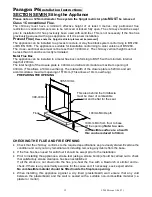
The front of the fireplace should be flat over an area sufficient to ensure a good seal with the closure
plate. The flat surface should extend for a height equal to that of the closure plate plus 20mm and for
a width equal to that of the closure plate plus 40mm.
The closure plate has an opening at the bottom for the gas feed pipe. The gap between the pipe and
this opening should be sealed with tape after connection. The closure plate must be fitted and sealed
to the fireplace opening using a suitable heat resistant material.
GAS SUPPLY ROUTING
Use rigid or semi
– rigid tube to connect the supply. Determine the gas supply pipe route to the
appliance before installing the fire.
MOUNTING THE
APPLIANCE
The flue spigot must be capable of passing through the closure plate with a minimum clearance of
50mm between its open end and the nearest obstruction. There must also be a minimum clearance
of 100mm between the back of the closure plate and the back of the catchment space. Place the fire
in position and mark the wall through the holes in the fixing brackets LH and RH of the firebox. Drill
and plug the holes using no 10 wall plugs. Place the fire in position and secure with four no 10 x 2in
Wood screws.
CONNECTING THE GAS SUPPLY
Note: -
An isolation valve may be fitted in the gas supply adjacent to inlet pipe.
For a concealed connection: -
Remove the burner assembly by removing four screws holding the burner tray to carrier.
fit the grommet over the pipe and seal around the inlet hole.
Refit the burner unit and make connection between the supply isolating valve and the burner
assembly inlet.
FITTING THE GLASS PANELS
.
Slide the LH and RH glass panels within the bottom location slots.
Fit the top retaining brackets over the two fixing studs LH & RH and finger tighten using the four
off 7mm nuts. (DO NOT TIGHTEN AT THIS STAGE).
Lay the fuel bed in accordance with section four fuel bed lay out.


