5910-A2-GZ40-00
May 2005
5
Cabling
See
Cables You Need
on page 2 for information about POTS splitter cabling.
Procedure
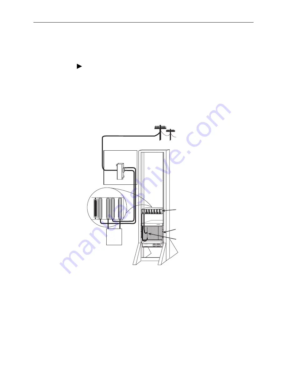
To cable the 5910 POTS splitter for each 24 subscriber lines:
1. Connect the DSL interface to the DSL ports connector of your DSLAM or BLC.
2. Connect the Line interface to the in-building POTS and ADSL CPE.
3. Connect the PSTN interface to the PBX or PSTN.
4. Secure each cable head with a cable tie and a cable head screw
Figure 3.
Typical Installation
Your CPE modems may require in-line filters. Consult your modem documentation.
Grounding
To comply with the Network Equipment Building Systems (NEBS) requirements, a
suitable ground must be provided. The 5910 can be grounded to the rack through
the mounting brackets, eliminating the need for a separate ground wire. Grounding
lugs are provided on the rear of the splitter modules to provide an accessible
termination point for cable shield/25th pair grounds. On the front, the 25th pair
(pins 25 and 50) are grounded internally.
05-17641
ALARMS
Major Minor
Fan
B
A
POWER
8820 BLC
Connecting
Block
Main Distribution
Frame
DSL
DSL
DSL
DSL
DSL
DSL
DSL
DSL
PSTN
Switch
8968 Line
Card
PSTN - 49
TO 72
LINE - 25
TO 48
PSTN - 25
TO 48
LINE - 1
TO 24
PSTN - 1
TO 24
Rear of
5910 Splitter
5910 Splitter


