UC300 Universal Converter
10
1. Clip the UC300 to the system panel box.
2. Plug in the PCS250/PCS250G cable between the UC300 serial port and the PCS250/PCS250G serial port. See
Figure 3
for the proper cable.
3. Connect the Tip and Ring from the UC300 to an outgoing telephone jack.
4. Connect the customer’s control panel Tip and Ring to the UC300 T1 and R1 terminals.
5. Connect the 12Vdc power supply to a supervised power supply.
6. Disconnect the cable from the UC300 Serial port and connect the IP150/UC300 to PCS250/PCS250G cable
from the 307USB to connect to your laptop. This will allow you to configure the setup using BabyWare. See
Figure 5
7. In BabyWare =>Accounts use Connection Option Serial.
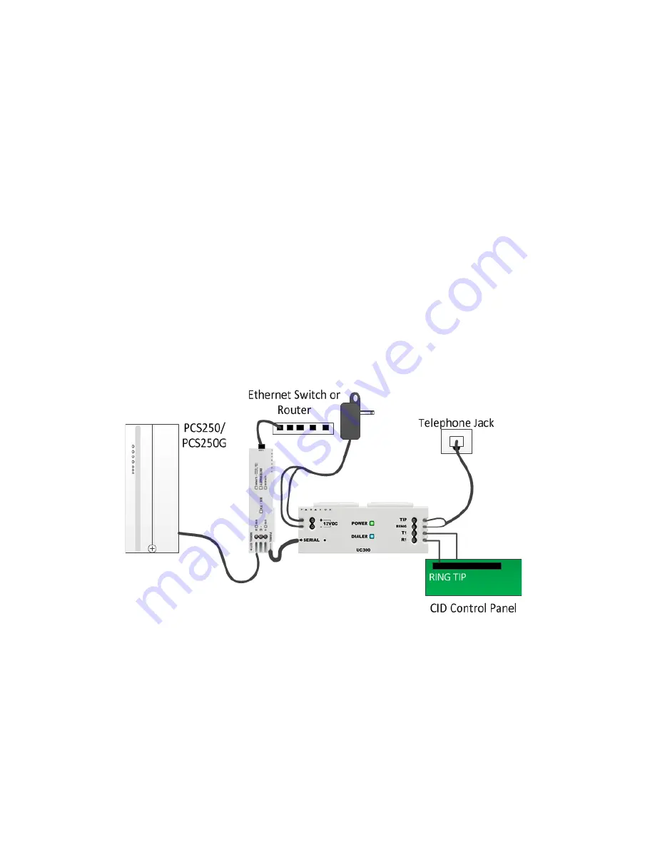
Option #3: Both IP150 and PCS250/PCS250G Communication Devices
1. Clip the UC300 to the system panel box.
2. Clip the IP150 to the system panel box near the UC300.
3. Plug in the UC300 to the IP150 using the IP150 panel port and the UC300 serial port. See
Figure 2
for the
proper cable.
4. Plug in the IP150 to the PCS250/PCS250G using the IP150 PCS250/PCS250G port and the PCS250/PCS250G
serial port. See
Figure 3
for the proper cable.
5. Connect the Tip and Ring from the UC300 to an outgoing telephone jack.
6. Connect the customer’s control panel Tip and Ring to the UC300 T1 and R1 terminals.
7. Connect the 12Vdc power supply to a supervised power supply.
8. Connect an Ethernet cable from the IP150 to the LAN.
9. In BabyWare =>Accounts use Connection Option IP Static and connect through the IP150.
Figure 6 – Connecting the UC300 with an IP150 and PCS250/PCS250G


