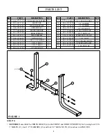
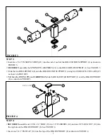
background image

STEP 3:

•  Insert two 3 X 2” INSERT GUIDES (21) into the end of each of the ROLLER PAD SUPPORT (1) as shown in

FIGURE 3.

FIGURE 3

•   

SECURELY 

assemble the SPRING PIN ASSEMBLY (22) to the ROLLER PAD SUPPORT (1). See FIGURE 3.
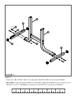
STEP 4:

•  Insert one 3 X 2” END CAP (18) into the top of the REAR UPRIGHT (6) as shown in FIGURE 4.

FIGURE 4

•  

SECURELY 

assemble on 3/8 X 1-1/4” BOLT (9), two 3/8” WASHERS (14), and one 3/8” LOCK NUT (12) into

the top hole on the REAR UPRIGHT (6). See FIGURE 4.

7

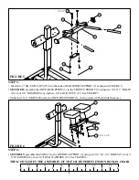
•   Pull back the SPRING PIN and 

CAREFULLY 

slide the ROLLER PAD SUPPORT (1) over the REAR UPRIGHT

(6). as shown in FIGURE 3.

•   Slide the two ROLLER PADS (8) onto the ROLLER PAD SUPPORT (1) using two STARLOCK COLLARS (19)

as  shown in FIGURE 3.

21

 6

 1

22

 8

19

14

18

12

 6

3/8 X 1-1/4”  9

Содержание 821

Страница 1: ...1 CLASS H PART 7349201 REV A Revision 09 24 02 USER S GUIDE WARNING Read and follow all directions for each step to insure proper assembly of this product 821 HYPEREXTENSION ROMAN CHAIR Version 821108...

Страница 2: ...use the machine if found in this condition DO NOT attempt to fix Notify your authorized ParaBody dealer 7 Inspect cables and their connections before using machine Pay particular attention to the cabl...

Страница 3: ...oper function 3 NOTE BOLT LENGTH IS MEASURED FROM THE UNDERSIDE OFTHE HEAD OFTHE BOLT BOLT LENGTH RULER This product must be assembled on a flat level surface to assure its proper function DO NOT secu...

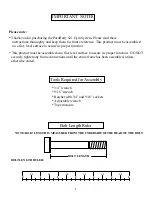
Страница 4: ...1 Square 1 X 1 4 1 2 3 4 5 1 5 4 3 2...

Страница 5: ...OVER CAP 3 X 2 END CAP STARLOCK COLLAR 1 X 8 GRIP 3 X 2 INSERT GUIDE 3 8 SPRINGPINASSY 2 SQ ENDCAP QTY 4 10 8 8 4 1 2 2 2 1 2 PART 6588710 6511709 6588309 6588509 6588909 6589109 6589321 6194601 32352...

Страница 6: ...UBES 2 as shown in FIGURE 2 0 1 2 3 4 5 6 1 2 1 2 1 2 1 2 1 2 1 2 FIGURE 2 SECURELY assemble the BASE TUBES 2 to the FRONT and REAR UPRIGHTS 5 6 using four 1 2 X 3 BOLTS 11 four 1 2 WASHERS 15 and fou...

Страница 7: ...of the REAR UPRIGHT 6 as shown in FIGURE 4 FIGURE 4 SECURELYassemble on 3 8 X 1 1 4 BOLT 9 two 3 8 WASHERS 14 and one 3 8 LOCK NUT 12 into the top hole on the REAR UPRIGHT 6 See FIGURE 4 7 Pull back t...

Страница 8: ...LY OF THE 821 HYPEREXTENSION ROMAN CHAIR Insert two 2 SQ END CAPS 23 into the ends of the HIP PAD SUPPORT 3 as shown in FIGURE 5 SECURELY assemble the PADS 7 to the HIP PAD SUPPORT 3 using two 3 8 X 1...

Страница 9: ...be purchased from your ParaBody customer service representative at 800 328 9714 Inspect equipment daily Tighten all loose connections are replace worn parts immediately Failure to do so may result in...

Страница 10: ...ve charges for returning parts to ParaBody and c all necessary or incidental costs related to installation of the replacement parts 6 SHIPPING If shipping by the Owners is deemed necessary in sole dis...

Страница 11: ...64 66 99 LIFE FITNESS CONSUMER DIVISION 14150 Sunfish Lake Blvd Ramsey Minnesota 55303 U S A Tel 763 323 4500 Fax 763 323 4797 800 328 9714 Toll free within the U S and Canada www parabody com 11 Lif...

Отзывы: