128-9108
7 of 24
Page 7
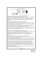
White Wire:
Parking Light Flasher Output
This wire is the normally open contact of the on board parking light flasher relay. Connect
this wire to the vehicle parking light feed wire.
7 Pin Accessory Input/Output Harness, Connector (P/N 4120107)
Brown/Red Wire:
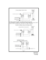
Brake Positive Inhibit Input
The Brown/Red wire provides an instant shutdown for the Remote Start Control module
whenever it gets + 12 volts. If the Brake lights switch in the vehicle sw 12 volts to
the brake light circuit, connect the Brown/Red wire to the output side of the brake switch.
This will allow the Remote Start to shut down if an attempt is made to operate the vehicle
without the key while running under the control of the Remote Start. In most vehicles, in
order to shift into gear, the brake pedal must be depressed. The brake input will in turn
cause the remote start unit to shut off.
Gray Wire:
Negative Inhibit Input
The Gray wire provides an instant shutdown for the Remote Start Control Module whenever
it is grounded. Connect the gray wire to the hood pin switch previously installed.
This wire must be routed through a grommet in the firewall and connected to the hood pin
switch. If the pin switch is to be used with an alarm system, connect this wire using a diode
assembly.
WARNING: DO NOT RELEASE THIS VEHICLE TO THE CONSUMER UNTIL YOU
CONFIRM THE OPERATION OF THE HOOD PIN SAFETY SHUT DOWN FEATURE.
IMPORTANT!
This connection is a safety wire and must be connected to a hood pin switch
and tested as described. Failure to do so may result in personal injury or property damage.
This wire may also be used if the vehicle brake light circuit switches ground to the brake
lights. An isolation diode must be used for ground switched brake light circuits and must be
connected to the output of the brake switch.
To test this circuit, while the vehicle is running under control of the remote start unit, open
the vehicle’s hood. The remote start unit should shut down immediately. If not, check the
wiring to the control module and the under hood pin switch.
WARNING: DO NOT RELEASE THE VEHICLE TO THE CONSUMER IF THIS CIRCUIT
DOES NOT PERFORM AS SPECIFIED.
Purple/White Wire:
Tachometer Input Signal
This wire will continually monitor the engine's tach rate while the unit is under power of
the Remote Start module. Route this wire to the vehicle ECM tach input or through the
firewall into the engine compartment and connect to the negative side of the ignition coil.
This Remote Start unit learns the tach rate of the vehicle and in most cases will operate
properly from one multi coil pack regardless of the number of cylinders.
If the vehicle has a single coil unit for each cylinder, it may be necessary to connect to
one of the vehicles electronic fuel injector wires for proper RPM signal.
Red/White Wire:
Delayed 250mA Pulsed Channel 3 Output
The Red/White wire supplies a 250mA ground pulsed output whenever channel three of the
receiver is accessed. Pressing the pre-programmed transmitter button for three seconds
will access this feature. This is a low current output and must be connected to a relay to
supply power to the trunk release or the circuit you wish to control. Connect the Red/White
wire to terminal # 86 of a VF45F11 P&B relay or equivalent. Connect terminal # 85 of the
Содержание PA-620C
Страница 5: ...128 9108 5 of 24 Page 5 ...


