background image

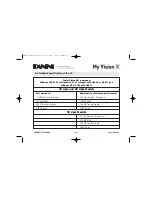
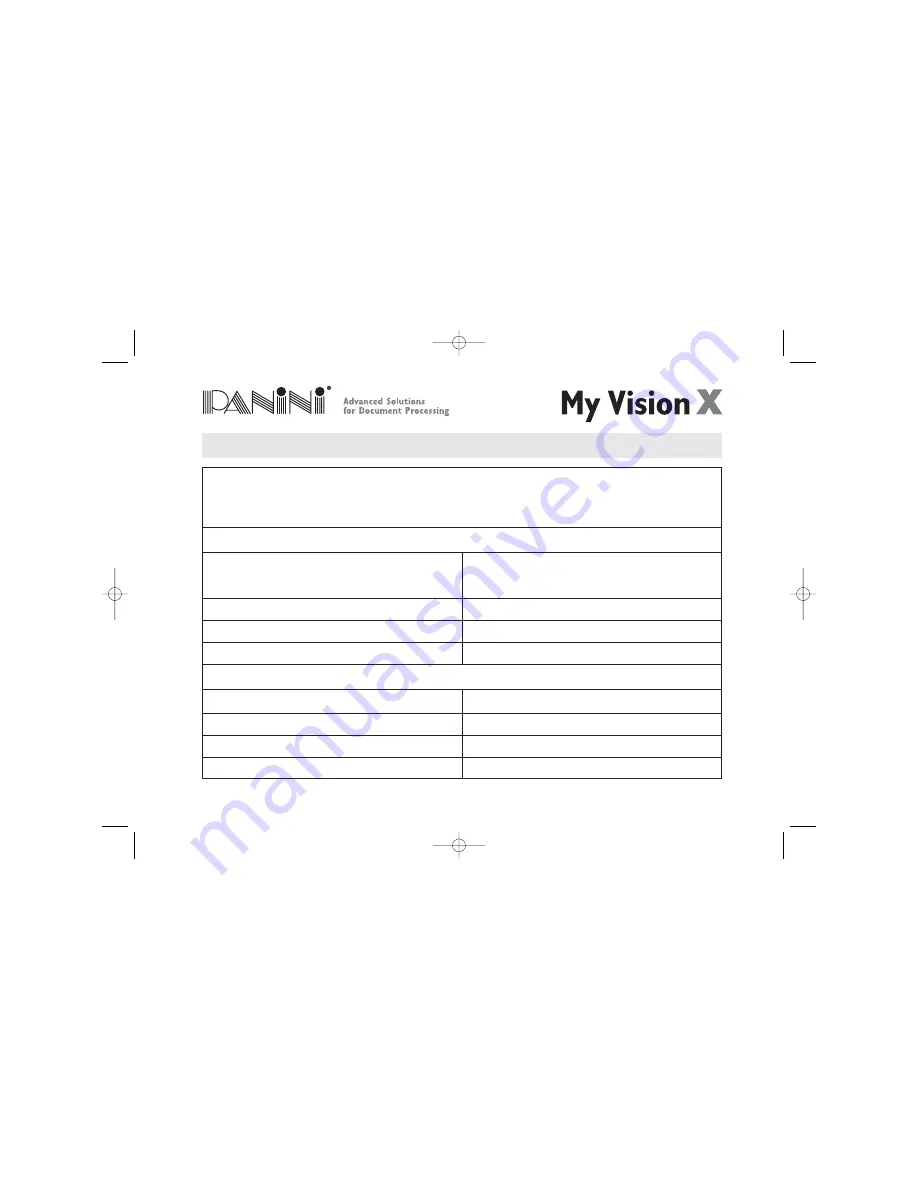
6.2 Technical Specification of the PC

Panini Vision API running on:

Windows 2000 SP3 or Windows XP SP1 or higher with USB2.0 or USB1.1 port

Windows NT 4.0 SP6 with USB1.1

30 dpm and 60 dpm Models

Recommended

Minimum (to obtain max performance)

1GHz Pentium IV processor

500 MHz Pentium III processor

256 MB RAM

128 MB RAM

200 MB free disk space

200 MB free disk space

USB2.0 port

USB2.0 port

90 dpm Models

1.2 GHz Pentium III processor

256 MB RAM

200 MB free disk space

USB2.0 port

Page 52

OPERATOR MANUAL

Specifications

Panini My VisionX_07.06  6-10-2006  10:21  Pagina 52

Содержание My Vision X

Страница 1: ...Panini My Vision X Operator Manual Panini My VisionX_07 06 6 10 2006 10 21 Pagina 1...

Страница 2: ...Internal Parts Description 3 Operating your Panini My Vision X 3 1 Document Support Installation 3 2 Extension Plate Installation 3 3 Power Cables Connection 3 4 USB 2 Cable Connection 3 5 HP C6602A I...

Страница 3: ...Jet cartridge 5 4 Cleaning the HP 51604A rev B Ink Jet Cartridge 5 5 Cleaning Photocells Detector 5 6 Replacing the Feeder and Separator Rollers 5 7 Cleaning the Reading Transport Belt 5 8 Install th...

Страница 4: ...i SpA or its subsidiaries is prohibited PANINI SpA PROVIDES THIS MANUAL AS IS WITHOUT WARRANTY OF ANY KIND EXPRESS OR IMPLIED INCLUDING BUT NOT LIMITED TO THE IMPLIED WARRANTIES OF MERCHANTABILITY AND...

Страница 5: ...interference when the equipment is operated in a commercial environment This equipment generates uses and can radiate radio frequency energy and if not installed and used in accordance with the instru...

Страница 6: ...EE Directive s crossed out dustbin symbol to indicate the requirement for separate collection of electrical and electronic equipment put on the market after August 13 2005 Panini guarantees the activa...

Страница 7: ...ces you to all the major components of your machine Chapter 3 Operating your Panini My Vision X describes simple installation procedures Chapter 4 Getting started explains how to operate the My Vision...

Страница 8: ...batch insertion by manually moving the pressure plate Options with limited feeder capacity are also available to cover specific customer needs MICR reading technology available with the Panini My Vis...

Страница 9: ...long hair or jewelry that can become entangled in moving parts Do not allow anything to rest on the power cord Do not locate the My Vision X where people may walk on the cord Always unplug the My Vis...

Страница 10: ...ent has been dropped or damaged If the equipment exhibits a distinct change in performance indicating a need for service Adjust only those controls and replace only those items that are covered by the...

Страница 11: ...ms Any of the Windows standard fonts can be used for printing endorsements The Panini My Vision X is connected to a PC via a USB2 0 interface 2 1 Packaging List The Panini My Vision X package includes...

Страница 12: ...ct the device from its packaging During unpackaging do not remove or pull the Mylar blades A B and C see Fig 4 Plastic handle Fig 3 1 Remove the Accessories box the operator manual and the power cable...

Страница 13: ...ibes the major components of the Panini My Vision X The component names introduced here and shown in the figures are used throughout this manual Document Pressure Plate Pocket Extension Extension Plat...

Страница 14: ...ator Roller 16 Rear Separator Roller 17 Pre magnetization Head 18 Synchronization Sensor 19 MICR Reading Head 10 U Track Wall 11 Transport Rollers 12 Ink Jet Cartridge Cradle 13 Front Image Camera 14...

Страница 15: ...nstallation Insert the Feeder Extension in the slot uncovered by pushing back the Document Pressure Plate Installation is correct if the Feeder Extension is at the same level of the entrance of the sc...

Страница 16: ...e extension plate face side up along the bottom side of the feeder extension into the support notches until the plate snaps into place Fig 8 The lock tabs should securely fit into the round holes and...

Страница 17: ...ovided in the Panini My Vision X packaging Using other power supplies could damage the unit 3 The My Vision X should be plugged into a dedicated electrical power outlet The power supply will be 100 24...

Страница 18: ...3 4 USB 2 Cable Connection Connect the USB 2 cable to the USB 2 0 port located on the rear side of the scanner then connect the other end of the cable to an available USB 2 0 port on the PC USB 2 cabl...

Страница 19: ...age Do not touch the ink with your fingers or clothing it will stain Angle the front side of the cartridge downwards and face the two pins with the two holes in the cradle Gently push down the rear si...

Страница 20: ...section 5 1 for details Take the additional plastic lever from the packaging install it on the left side of the cartridge cradle and pull it down Take a new Ink Jet cartridge out from its package Do...

Страница 21: ...rocessed in the pocket Move the pocket extension left or right until a space of 5 mm 1 4 is available between the leading edge of the document and the end of the pocket extension 5mm 1 4 Page 21 OPERA...

Страница 22: ...o on line when the control application starts and goes offline when the control application shuts down If you want to force the reader to go offline even when the application is on press the rear butt...

Страница 23: ...y Vision X is online and the feeder is empty Off Blinking The My Vision X is online and the feeder contains documents ready to feed On Off Interlock switches are activated and an external plastic cove...

Страница 24: ...he bottom edges by repeatedly tapping the bottom edge of the documents on a hard flat surface see Fig 17 3 Repeatedly tap the leading edge of the documents on a hard flat surface see Fig 18 4 Check bo...

Страница 25: ...hes of up to 30 by inserting the documents all the way into the feeder Fig 19 The documents must be inserted into the feeder so that the leading edge fits between the two black lines shown in Fig 20 D...

Страница 26: ...rtion Holds up to 30 documents for automatic batch one hand insertion without moving the pressure plate Holding up to 100 documents by pushing back the pressure plate before inserting checks into the...

Страница 27: ...ed The feeder is designed so that checks can be loaded continuously while the scanner is processing This can be done by inserting checks behind those already present in the feeder Fig 22 Panini My Vis...

Страница 28: ...commendations Remove the documents when the pocket is nearly full Jams occur when the pocket is too full No pocket full sensor is available Occasionally verify that the endorsements are clearly printe...

Страница 29: ...the track by pressing Eject in your application In case of unsuccessful operation apply the following suggestions 1 Extract the jammed document simply by pulling it out with your fingers see Fig 23 2...

Страница 30: ...transport See Fig 25 4 After the jam is removed install the inner cover by following the instructions below a Open the pocket extension b Insert the two reference shafts in the corresponding housings...

Страница 31: ...ack to its original position Take care to ensure that the inner cover stays behind the scanner which is indicated by a black area see Fig 27 The inner cover grid must be inserted behind the scanner bl...

Страница 32: ...at the two plastic springs are aligned properly as shown in Fig 28 5 In the event that the outer cover has to be removed first disconnect the USB and power cables and then lift the outer cover as show...

Страница 33: ...s listed in chapter 5 1 2 7 If the jam occurs in the image camera area it is advisable to open the front image camera see Fig 31 so that the document can easily be removed Close the image camera caref...

Страница 34: ...two shafts with the holes in the bottom cover of the unit Fig 32 Insert the two teeth located on each side of the outer cover in the bottom cover and lock it Fig 33 and 34 9 Reconnect the USB and pow...

Страница 35: ...oing maintenance remember to disconnect the USB 2 and power cables from the device Note The parts accessible to the operator for cleaning or jam removal are identifiable by green stickers Green sticke...

Страница 36: ...the Transport Dust lint and small particles can get into the track area Clean this area as follows 1 Remove the inner and outer covers by pulling up on the covers as illustrated below Fig 37 Fig 38 P...

Страница 37: ...er and remove the U track 3 Inspect and clean the entire track area from beginning to end 4 Remove staples paper clips rubber bands and pieces of paper that may have accumulated during use 5 Using a c...

Страница 38: ...he rail D Fig 44 and align the U track Fig 41 Push back the U track Fig 45 until the lever E Fig 41 locks the unit in place Make sure that the pin B Fig 43 is inserted in the receptacle A Fig 42 Fig 4...

Страница 39: ...ly A comes away from the U track insert the low mylar spring in the lateral slots B and the pad housing in the reference pins C Gently press down until the pad housing stops on the top of the U Track...

Страница 40: ...open the front image camera Fig 48 and remove any debris and dust 2 Clean the Contact Image Sensors with a soft lint free cloth dampened with Isopropyl Alcohol or with eye glass cleaner Fig 49 Fig 48...

Страница 41: ...e cloth with deionized or distilled water 4 Hold the dampened cloth in contact with the nozzles for a few seconds 5 Then gently wipe the nozzle plate in the direction of the paper movement Do not wipe...

Страница 42: ...old the dampened cloth in contact with the nozzles for a few seconds Fig 51 5 Then gently wipe the nozzle plate in the direction of the paper movement Do not wipe the electrical contact area 6 If ink...

Страница 43: ...ll Detectors The six photocells emitter and receiver are identified with black circles in Fig 52 below Using a container of canned air and nozzle spray the sensors to remove any dust Also a dry soft c...

Страница 44: ...Separator Roller rings due to normal wear 1 Open the inner and outer covers 2 Carefully lift the rings off the rollers See the arrows in Fig 53 54 and 55 Page 44 OPERATOR MANUAL Maintenance Fig 53 Fig...

Страница 45: ...the new separator rings on the hubs by pressing down on the surface of the rings making sure the rings are installed flat on their seats The feeder ring must be rolled onto the black pulley Fig 56 Pan...

Страница 46: ...e reading transport belt to remove extraneous magnetic ink or iron dust Clean the external surface of the belt with a soft lint free cloth dampened with Isopropyl Alcohol Turn pulley A counterclockwis...

Страница 47: ...ns below 1 Open the pocket extension 2 Insert the two reference shafts in the corresponding housings found in the inner cover Fig 58 3 Push down on the inner cover until it stops ensuring that the inn...

Страница 48: ...the two plastic springs are properly aligned as shown in Fig 60 Page 48 OPERATOR MANUAL Maintenance Fig 60 Scanner Inner cover The inner cover grid must be inserted behind the scanner black Panini My...

Страница 49: ...e two shafts with the two holes in the bottom cover of the unit Fig 61 Push the cover down 6 Insert the two teeth located on each side of the outer cover in the bottom cover and lock it see Fig 62 and...

Страница 50: ...Length Min 80 mm 3 14 Max 235 mm 9 25 Weight Min 60 gr m2 16 Max 120 gr m2 32 INTERFACE USB2 0 port Backward compatible with USB1 1 RS232 Port for external device connection SW FW developments on requ...

Страница 51: ...Recognition CODE 39 CODE 128 INTERLEAVED 2 5 EAN8 EAN13 UPCA UPCE DIAGNOSTIC FEATURES On board Diagnostics Tests the functionality of the scanner Power on Self Testing Automatic self testing and phot...

Страница 52: ...dpm Models Recommended Minimum to obtain max performance 1GHz Pentium IV processor 500 MHz Pentium III processor 256 MB RAM 128 MB RAM 200 MB free disk space 200 MB free disk space USB2 0 port USB2 0...

Страница 53: ...d Checks The SD scanner unit is designed for single document processing exclusively All references to preparing and processing batches of multiple items in this section is not relevant to the SD versi...

Страница 54: ...ow to install the My Vision X AGP Ink Jet cartridge Use only HP Q2344A cartridges Black 1918 Dye Panini P N CA 00140 00 Remove the new print cartridge from its package and gently remove the transparen...

Страница 55: ...cloth de ionized water is best wipe slowly across the long axis with the print cartridge facing down as shown The damp cloth should draw ink from the cartridge flushing out the nozzles Do not apply ex...

Страница 56: ...Notes Panini My VisionX_07 06 6 10 2006 10 21 Pagina 56...

Отзывы: