SMARTZONE UPS USER MANUAL
13
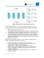
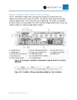
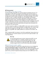
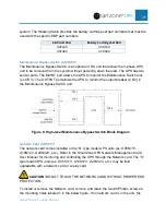
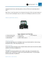
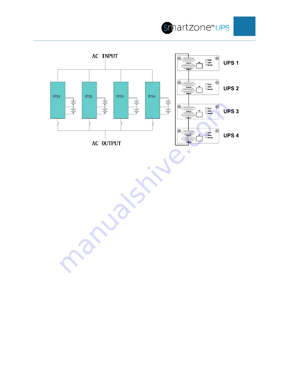
Figure 2: Parallel System Power/Control Connections
Parallel Mode System Restrictions
To ensure that all UPS units in the Parallel mode system configuration are equally
utilized and comply with relevant wiring rules, the following restrictions must be met:
•
All UPS units must be of the same rating.
•
The input main of all the UPS units must be connected to a common input bus.
•
The input bypass of all the UPS units must be connected to a common input bus.
•
The output of all the UPS units must be connected to a common output bus.
•
The length and specification of all UPS power cables (main input, bypass input,
and the output cables) must be the same type and same length. This helps to
facilitate load sharing and zero crossing alignment between the UPS units when
operating in Parallel Mode.
Parallel Mode Setup and Startup
Each UPS unit in the Parallel mode system must be properly configured before the
outputs of the Parallel mode system are connected.
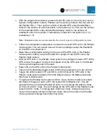
•
Confirm that all breakers in the Parallel Mode system are open.
•
Confirm that the input power connections and the input phase sequence is
correctly connected. Leave outputs disconnected.
•
Confirm that the +/- battery voltage of all EBP groups are correct.
•
Confirm that the parallel control cables are connected in a ring configuration
between all UPS units in the Parallel mode system (refer to the control
connections in
).
•
All parallel mode system setting must be completed on each unit before the
outputs are connected.


