OMAP
TM
4 PandaBoard System
Reference Manual
Revision 0.4
September 22, 2010
DOC-21010
Page 25 of 83
ID
IO
VBUS
P
VBUS
1
GND
5
F1
SW_EN
I
SW_IN
I
(U22)
SW_OUT
O
R150
(P3)
(J18)
(U23)
R162
R164
FDC6330L
(U17)
FDC6330L
(U15)
TPS3803G15
(U20)
DC_HST_5V
(to USB Host Ports)
LDO_OUT
O
LDO_IN
I
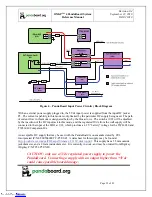
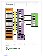
Figure 4 – PandaBoard Input Power Circuitry Block Diagram
With an external power supply plugged in, the 5Vdc input power is supplied from the input DC jack at
P3. The current capability in this mode is only limited by the particular DC supply being used. The path
of current flow in this mode is designated below by the blue arrows. The switch at U22 will be disabled
by the insertion of the DC input jack in this mode, and the regulated 5Vdc from the wall supply will be
connected to the input of the LDO at U23, which provides a 4.2V “battery” voltage for the TWL6030 and
TWL6040 Companion ICs.
An acceptable DC supply that may be used with the PandaBoard is one manufactured by CUI,
Incorporated (P/N ETS050400UTC-P5P-SZ). A datasheet for this supply may be found at
http://products.cui.com/getPDF.aspx?filename=20+W+desktop.pdf
. This supply has a 5.5mm outside
jack diameter, and a 2.1mm inside diameter. It is currently in stock, and may be ordered from Digikey
(Digikey P/N T951-P5P-ND).
CAUTION: only use a 5Vdc regulated power supply to power the
PandaBoard. Connecting a supply with an output higher than +5Vdc
could cause possible board damage.
Downloaded from
Downloaded from
Downloaded from
Downloaded from
Downloaded from
Downloaded from
Downloaded from
Downloaded from
Downloaded from
Downloaded from
Downloaded from
Downloaded from
Downloaded from
Downloaded from
Downloaded from
Downloaded from
Downloaded from
Downloaded from
Downloaded from
Downloaded from
Downloaded from
Downloaded from
Downloaded from
Downloaded from
Downloaded from


