31
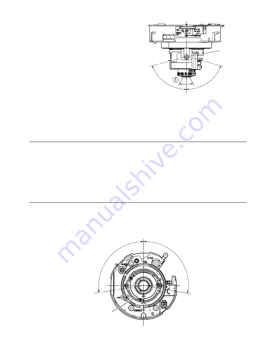
Vertical position (Tilting)
Loosen the tilting lock screws (x2), and rotate
the tilting table to adjust the tilting direction.
(Adjustable range: ±75 °) Since a variable focal
lens is used, it is possible to change the angu-
lar field of view. This lens can also be rotated in
the reverse direction, but the image azimuth is
reversed. In this case, hold down the auto
focus (AF) button/upside-down button for 5
seconds or more. The upside-down function
starts operating and the image azimuth is mod-
ified.
<Lens angular field of view (
q
Angle)>
Horizontal: 24.20° (TELE) to 86.60° (WIDE)
After adjustment, tighten the tilting lock screws (x2) to fix the tilting table.
(Recommended tightening torque: 0.59 N·m {0.44 lbf·ft})
Note:
• When the tilting table is turned to the edge of the adjustable range (±75 °), it must be noted
that the shadow of the dome cover may be projected.
• When the camera is installed to a wall, the image is turned upside down in the default settings.
The way the image is displayed can be corrected in three ways: rotating the panning table 180°
clockwise, holding down the auto focus (AF) button/the upside-down button for 5 seconds or
more and operating the upside-down function, or selecting "On" for "Upside-down" from the
setup menu. For information about performing the "Upside-down" setting from the setup
menu, refer to the Operating Instructions (included in the CD-ROM).
Image tilt adjustment
Rotate the azimuth adjustment ring to adjust the azimuth angle of the image.
(Adjustable range: ±100 °)
+75 °
–75 °
Adjustable range
Tilting lock
screws (x2)
–100 °
+100 °
Adjustable range
Azimuth adjustment ring


