background image

71

7. Select a desired recording event by performing one of

the following.

• Move the 3D joystick controller to up or down.
• Rotate the JogDial clockwise or counterclockwise.
• Press the + or – button.

Note:

To move to the next or previous page, perform

either of the following.

• Move the zoom wheel controller to the right or left.
• Rotate the shuttle ring clockwise or counterclock-

wise.

8. Press the PLAY button.

The playback of selected recording event will start.

9. To exit the search mode, press the MON (ESC) or EXIT

button. 
The live image will be displayed again on the monitor.

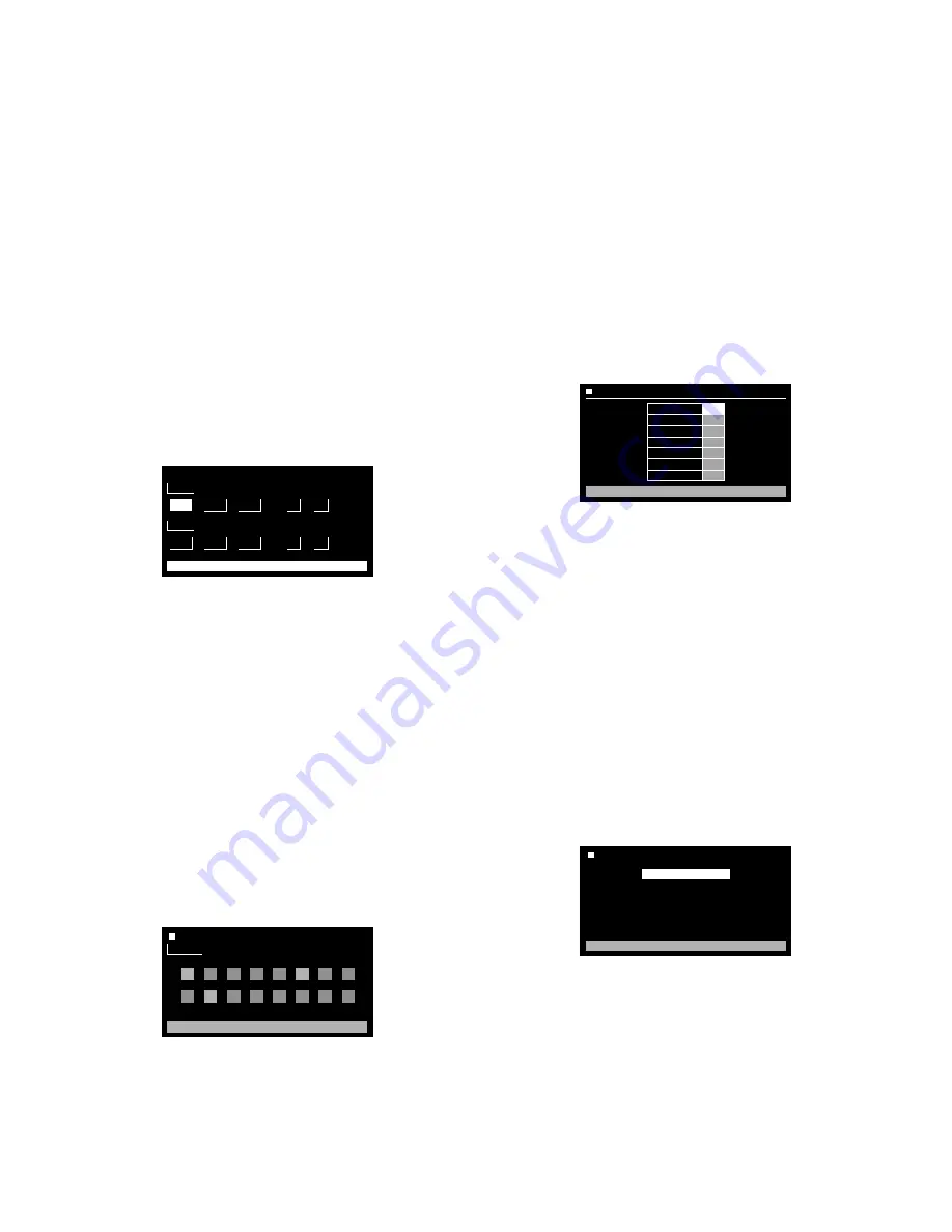
Searching filter windows

Available controls and functions (TIME&DATE FILTER-
ING window)

<Main unit>
JogDial clockwise:

Increments a parameter.

JogDial counterclockwise:

Decrements a parameter.

+ button: 

Increments a parameter.

– button: 

Decrements a parameter.

CAM (SET) button:

Executes the filtering.

MON (ESC) or EXIT button:

Cancels the filtering and

returns to the upper menu.

<3D joystick unit>
3D joystick upward (

D

):

Moves the cursor up.

3D joystick downward (

C

):

Moves the cursor down.

3D joystick leftward (

A

):

Moves the cursor to the left.

3D joystick rightward (

B

):

Moves the cursor to the

right.

Available controls and functions (CAMERA FILTERING
window)

<Main unit>
JogDial clockwise or counterclockwise:

Changes the

camera number, pointed by the cursor, between On
and OFF.

+ button: 

Increments a parameter.

– button: 

Decrements a parameter.

CAM (SET) button:

Executes the filtering.

MON (ESC) or EXIT button:

Cancels the filtering and

returns to the upper menu.

<3D joystick unit>
3D joystick upward (

D

):

Moves the cursor up.

3D joystick downward (

C

):

Moves the cursor down.

3D joystick leftward (

A

):

Moves the cursor to the left.

3D joystick rightward (

B

):

Moves the cursor to the

right.

Available controls and functions (REC EVENT FILTER-
ING window)

<Main unit>
JogDial clockwise:

Increments a parameter.

JogDial counterclockwise:

Decrements a parameter.

+ button: 

Increments a parameter.

– button: 

Decrements a parameter.

CAM (SET) button:

Executes the filtering.

MON (ESC) or EXIT button:

Cancels the filtering and

returns to the upper menu.

<3D joystick unit>
3D joystick upward (

D

):

Moves the cursor up.

3D joystick downward (

C

):

Moves the cursor down.

3D joystick leftward (

A

):

Moves the cursor to the left.

3D joystick rightward (

B

):

Moves the cursor to the

right.

Available controls and functions (TEXT FILTERING win-
dow)

<Main unit>
JogDial clockwise:

Increments a parameter.

JogDial counterclockwise:

Decrements a parameter.

+ button: 

Increments a parameter.

– button: 

Decrements a parameter.

CAM (SET) button:

Executes the filtering.

MON (ESC) or EXIT button:

Cancels the filtering and

returns to the upper menu.

START

JAN

1

03

SET : [SET]  CANCEL : [ESC]

00

00

■ 

TIME&DATE FILTERING

.

.

:

AM

END

JAN

1

03

0

00

.

.

:

AM

1

2

3

4

5

6

7

8

9

10

11

12

13

14

15

16

CAMERA FILTERING

CAMERA

SET : [ SET ]      CANCEL : [ ESC ]

SET : [ SET ]      CANCEL : [ ESC ]

REC EVENT FILTERING

OFF

ON
ON
ON
ON
ON
ON

EMERGENCY
VMD
TERMINAL
COMMAND
VIDEO LOSS
MANUAL
SCHEDULE

TEXT FILTERING

WITHOUT TEXT

SET : [ SET ]      CANCEL : [ ESC ]

Содержание WJMPU955A - CENTRAL PROCESSING UNIT

Страница 1: ...lease read these instructions carefully and save this manual for future use No model number suffix is shown in this manual Central Processing Unit WJ MPU955A FAN ALARM HDD ACTIVE OPERATE Central Proce...

Страница 2: ...folgenden Normen oder normativen Dokumenten bereinstimmt Gem den Bestimmungen der Richtlinie 73 23 EEC und 89 336 EEC Nous d clarons sous note seule responsabilit que le produit auquel se r f re la pr...

Страница 3: ...ction manual may cause harmful interference to radio communications Operation of this equipment in a residential area is likely to cause harmful interference in which case the user will be required to...

Страница 4: ...your outlet consult an electrician for replacement of the obsolete outlet 10 Protect the power cord from being walked on or pinched particularly at plugs convenience receptacles and the point where th...

Страница 5: ...OF THE PRODUCT BY THE USER 4 INCONVENIENCE OR ANY LOSS ARISING WHEN IMAGES ARE NOT DISPLAYED DUE TO ANY REASON OR CAUSE INCLUDING ANY FAILURE OR PROBLEM OF THE PRODUCT 5 ANY PROBLEM CONSEQUENTIAL INCO...

Страница 6: ...Admin Console 33 Time Management Utility 33 Digital Disk Recorders 34 CONNECTION OF WJ SX650 512 x 64 FULL MATRIX SYSTEM 35 Connection with System Devices 36 System Controllers 36 Matrix Switcher WJ...

Страница 7: ...e Search Playback 74 System Function 75 Other Functions 75 Menu Function Descriptions 77 Menu Functions 77 To Recall Menu Functions 77 Menu Function Details 78 Camera Setup 78 Auto Mode 78 BW Mode 78...

Страница 8: ...oder WJ GXE900 and MPEG2 Decoder WJ GXD900 WJ MPU955A can control up to 1 024 cameras and 256 monitors with 64 system controllers Note MPEG2 Encoder WJ GXE900 and MPEG2 Decoder WJ GXD900 support the N...

Страница 9: ...and humidity below 90 The input power source for NTSC model is 120 V AC 60 Hz for PAL model is 220 V 240 V AC 50 Hz We recommend that you make a note of your set tings and save them This will help you...

Страница 10: ...ted system NTSC model only SX850 Panasonic System850 Large Scale Matrix System Old generation SX650 Panasonic Matrix Switcher WJ SX650 Series Caution s Caution statements identify conditions or practi...

Страница 11: ...cation about System Units NTSC model only Notification about WJ GXD900 and WJ GXE900 firmware versions To use WJ GXD900 and WJ GXE900 NTSC model only devices with WJ MPU955A the firmware of WJ GXD900...

Страница 12: ...12 This page intentionally left blank...

Страница 13: ...13 FEATURES OF WJ SX650 512 x 64 FULL MATRIX SYSTEM AND GX SYSTEM...

Страница 14: ...es only the operator with the higher priority gets the resources Video Switch and Video Routing This function allows operators to switch video from one video source to another if the permission is gra...

Страница 15: ...the highest priority operator releas es the alarm The alarm controls include Arm and disarm alarms Acknowledge active alarms Reset acknowledged or active alarms The system also supports automatically...

Страница 16: ...2 1 GGV G POWER ON OFF SIGNAL AUDIO IN VIDEO OUT VIDEO IN 100BASE TX RS 485 TERM 1 GND 2 3 ON OFF 4 ALARM IN TRIGGER OUT RESET 4 3 2 1 G 4 3 2 1 GGV G POWER ON OFF SIGNAL AUDIO IN VIDEO OUT VIDEO IN 1...

Страница 17: ...ON OFF 4 ALARM IN TRIGGER OUT RESET 4 3 2 1 G 4 3 2 1 GGV G POWER ON OFF SIGNAL AUDIO IN VIDEO OUT VIDEO IN 100BASE TX RS 485 TERM 1 GND 2 3 ON OFF 4 ALARM IN TRIGGER OUT RESET 4 3 2 1 G 4 3 2 1 GGV G...

Страница 18: ...supports Panasonic Ethernet controllers Up to 64 system controllers are connectable in the system IP addresses will be automatically provided to each system controller during the communication with th...

Страница 19: ...32 Coaxial Cables WJ PB65E01 WJ PB65E01 WJ PB65E01 Not used Not used Video Input Board 2 Video Input Board 1 Video Output Board 2 Video Output Board 1 Not used Not used Video Input Board 8 Video Input...

Страница 20: ...20 This page intentionally left blank...

Страница 21: ...21 21 21 DETAILED PRODUCT DESCRIPTION...

Страница 22: ...and Their Functions Layout The following diagrams are the front panel and the rear panel of the WJ MPU955A Front View Front panel attached Front panel detached Rear View Central Processing Unit WJ MP...

Страница 23: ...ther Redundant System YES or Standard System NO The factory default setting is NO Refer to p 28 for details i Mode Selector REDUNDANT AUTO MANUAL This selector can be set for either the manual or auto...

Страница 24: ...24 This page intentionally left blank...

Страница 25: ...25 INSTALLATIONS...

Страница 26: ...d 4 pcs Refer to the following illustration Important The cooling fan inside the unit is perishable and must be replaced periodically If the rack is subject to vibration secure the rear of the unit to...

Страница 27: ...27 CONNECTION OF GX SYSTEM NTSC MODEL ONLY...

Страница 28: ...TENTION CAUTION CONNECTTO SPECIFED CLASS 2 POWER SUPPLY ONLY SEE MANUAL Refer to the diagram CONTROLLER No Maintain the switch setting as 1 WV CU 950 MODE MODE 1 2 3 4 5 6 7 8 OFF ON Set as shown belo...

Страница 29: ...c Switchover Operation 1 Connect the 9 pin D sub cross cable locally procured between the SERIAL 2 ports of both CPUs 2 Set the REDUNDANT AUTO MANUAL selector to AUTO 3 Reboot the Standby CPU When the...

Страница 30: ...must be entered into the digital device database In the admin con sole select Switch Nodes from the Domain menu select Digital GX from the sub menu that appears and then enter the infor mation for the...

Страница 31: ...EO IN 100BASE TX RS 485 TERM 1 GND 2 3 ON OFF 4 ALARM IN TRIGGER OUT RESET 4 3 2 1 G 4 3 2 1 GGV G POWER ON OFF SIGNAL AUDIO IN VIDEO OUT VIDEO IN 100BASE TX RS 485 TERM 1 GND 2 3 ON OFF 4 ALARM IN TR...

Страница 32: ...T MIX RESET 1000BASE T 100BASE TX V G QUAD 10BASE T 100BASE TX SERIAL 2 1 OTHER SYSTEM DEVICE SYSTEM CONTROLLER POWER ON AC IN OFF SIGNAL GND WJ GXD900 WJ MPU955A Switching HUB 10BASE T 100BASE TX SER...

Страница 33: ...ed on the same computer that runs the admin console To connect the TMU to the CPU you should select IPA setup from the TMU main menu and enter the IP address of the CPU Refer to Time Management Utilit...

Страница 34: ...tor needs to set up the IP address of digital disk recorder Refer to the Operating Instructions of digital disk recorder for details Notes The IP Address setting in SETUP MENU of digital disk recorder...

Страница 35: ...35 CONNECTION OF WJ SX650 512 x 64 FULL MATRIX SYSTEM...

Страница 36: ...1 ALARM OUT 2 ALARM OUT 1 SERIAL VS OUT VS IN VS OUT THRU Video Output Board 1 Only IN X 1 16 15 14 13 12 11 10 9 CAMERA IN 8 7 6 5 4 3 2 1 32 31 30 29 28 27 26 25 24 23 22 21 20 19 18 17 NETWORK OUT...

Страница 37: ...EO OUT 3 VIDEO OUT 4 VIDEO OUT 2 IN X 2 VIDEO OUT 1 ALARM IN EXTENSION 3 IN EXTENSION 2 IN 4 MODE RS485 CAMERA RS485 CAMERA 3 MODE MODE MODE 2 1 IN C 3 MODE MODE MODE MODE DATA DATA EXTENSION 1 TERM O...

Страница 38: ...Board 2 Note To make the video switching work as non blocking the all 32 outputs of SubNode 1 and SubNode 2 should be connect ed to SubNode 3 inputs 1 3 Video Connection between SubNode 4 and SubNode...

Страница 39: ...O OUT 3 Input Board 4 Camera Input Connecters 17 to 24 Input Board 4 VIDEO OUT 4 Input Board 4 Camera Input Connecters 25 to 32 Input Board 4 VIDEO OUT 1 Input Board 5 Camera Input Connecters 1 to 8 I...

Страница 40: ...ters 17 to 24 Input Board 4 VIDEO OUT 4 Input Board 4 Camera Input Connecters 25 to 32 Input Board 4 VIDEO OUT 1 Input Board 5 Camera Input Connecters 1 to 8 Input Board 5 VIDEO OUT 2 Input Board 5 Ca...

Страница 41: ...41 CONFIGURATION DETAILS...

Страница 42: ...System Configuration screen Upload the SYS INI file from the CPU using the Get from CPU button in the SYS Transfer section Modify the system configuration file that appears in the document area of th...

Страница 43: ...C model only Interface1 172 18 0 1 255 255 0 0 172 18 0 1 Interface1 is an interface for system controller Interface2 172 16 192 1 255 255 0 0 172 16 192 1 Interface2 is used for SNMP SNTP feature Not...

Страница 44: ...tly supported Set SSntp to the same interface_num for all system CPUs SSntp 2 Not currently supported Set SNMPAgent to the same interface_num for all system CPUs SNMPAgent 2 1 means interface1 in INTE...

Страница 45: ...Minutes Frequency to copy to HD 1 30 min Note Values outside this range 1 min Days days to save on HD 5 30 Mode 0 off default 1 on UserLog 10 7 1 SwLog 10 7 0 AlarmLog 10 7 1 VideoLossLog 10 7 1 RS232...

Страница 46: ...ers on this unit Cameras num of cameras on this unit Monitors num of monitors on this unit Keyboards 64 Cameras 1024 Monitors 256 ROUTING section Note This section should not be changed This section a...

Страница 47: ...ast ServerMode mode to expose its timestamp to other units modes 0 Off 1 On default InternalFrequency time frequency of sync secs default is 600 sec 10 min VALUES FOR EXTERNAL CONNECTION NTPServerIPA...

Страница 48: ...00 00 00 00 00 ID 1 2 3 4 5 6 7 8 9 10 11 12 13 511 512 Logical 1 2 3 4 5 6 7 8 9 10 11 12 13 511 512 Switch SX650 SX650 SX650 SX650 SX650 SX650 SX650 SX650 SX650 SX650 SX650 SX650 SX650 SX650 SX650...

Страница 49: ...5 63 64 Area 0 0 0 0 0 0 0 Local 1 2 3 4 5 63 64 Switch SX650 SX650 SX650 SX650 SX650 SX650 SX650 Port 1 2 3 4 5 63 64 ID 100 955 Password 100 955 Priority 100 3 00 00 00 00 00 00 Name Normal Super Cl...

Страница 50: ...C 1 2 3 4 0 1 CAMERAS Control Video OSD 1 2 3 4 5 6 7 8 9 10 11 12 13 14 15 Logical 1 2 3 4 5 6 7 8 9 10 11 12 13 14 15 Switch GX GX GX GX GX GX GX GX GX GX GX GX GX GX GX Ports 1 2 3 4 5 6 7 8 9 10 1...

Страница 51: ...al MAC address that is indicated on a product should be entered in the EA field 1 2 3 4 5 6 7 8 Area 0 0 0 0 0 0 0 0 Local 1 2 3 4 5 6 7 8 Switch GX GX GX GX GX GX GX GX Port 1 2 3 4 5 6 7 8 MONITORS...

Страница 52: ...AL RECORDERS 1 15 16 14 13 10 9 7 12 11 6 1 2 3 4 5 8 ID Logical 1 Model WJ HD316A Video Switch Port GX 16 IPA 172 18 0 60 Unit Address 1 Digital Bitrate 6 144 Channels 15 14 13 10 9 7 12 11 6 1 2 3 4...

Страница 53: ...53 OPERATING PROCEDURES with WV CU950...

Страница 54: ...ntered a camera number or monitor number etc that is not existing Busy When a selected monitor is controlled by a higher level user blinks on the LCD You cannot control the monitor When a selected cam...

Страница 55: ...conds on the LCD In this case retry the login procedure Login and Logout Note If you perform the login procedure after resetting the CPU unit or turning on the power of CPU unit the LCD display may re...

Страница 56: ...te To select the next or previous camera number press the or button Monitor Selection and Camera Selection Monitor Lock Monitor lock is the function to retain other operators control of a monitor even...

Страница 57: ...ent of LCD Display and Buzzer You can perform the settings of LCD brightness LCD contrast alarm buzzer or button buzzer Refer to WV CU950 Operating Instructions for how to adjust Display Setting for C...

Страница 58: ...xposure Note To return the lens iris to the factory default status press the A button of 3D joystick unit Pan Tilt Control Manual Operation 1 Select the desired monitor and camera Refer to p 56 Monito...

Страница 59: ...T button The camera will move to the preset position and the image of selected preset position will be displayed on the active monitor Note To call preset positions you must set preset position number...

Страница 60: ...xiliary control devices The following procedure is available when an auxiliary control device such as Receiver WV RC150 is connected to a system unit Operating Procedure 1 Select the desired monitor a...

Страница 61: ...desired camera function number by pressing the numeric buttons Note When you select a wrong number press the CLEAR button to clear the numeric input 3 Pres the CAM FUNC SYS FUNC button CamF nnn will a...

Страница 62: ...e only if a Group Sequence has been previously established through the admin console A Group Sequence determines the assignment of monitors and cameras 1 Press the numeric buttons to select a desired...

Страница 63: ...ompounded from the Character Board that is installed on the Camera Input Board Confirm the setting in the admin console for details 1 Select the desired monitor Refer to p 56 Monitor Selection 2 Press...

Страница 64: ...00512 MON Alarm00001 CAM 0123 Disarm 00512 MON Alarm Exit CAM 0123 Unit 01 00512 Example of Alarm Input and Resulting Alarm Activation The following is an example of an alarm input and the resulting...

Страница 65: ...mera Site Accessories Control Note To select another alarm press the ALARM ALM SUSPEND button The ACK status will be canceled cancelled Then enter the alarm action number by pressing the numeric butto...

Страница 66: ...for alarm response CLEARED Auto arming is not set in the admin con sole DATE TIME Date and time when alarm state changes 3 To display the next page press the button To display the previous page press...

Страница 67: ...The following are the operating procedures of WJ HD300A Series via system controller Note Refer to the Operating Instructions of recorder for details on each function Normal Playback 1 Select the reco...

Страница 68: ...back images can be electrically zoomed besides a camera s optical zooming 1 Select the recorder Refer to p 67 Recorder Selection 2 Press the PLAY PAUSE button To start the playback press the PLAY PAUS...

Страница 69: ...Note While holding down the SHIFT button the LCD dis play will become as follows Available buttons and functions Common F1 button Thumb or List Changes the monitor display between the recording event...

Страница 70: ...hing mode 3 Select a desired searching filter by moving the joystick rightward or leftward Note The illustration is an example in which CAMERA has been selected for the searching filter 4 To determine...

Страница 71: ...ents a parameter CAM SET button Executes the filtering MON ESC or EXIT button Cancels the filtering and returns to the upper menu 3D joystick unit 3D joystick upward D Moves the cursor up 3D joystick...

Страница 72: ...B Moves the cursor to the right 5 Press the CAM SET button The motion detection area setup window will be dis played Note If no image was recorded in the time range set in step 4 the motion detection...

Страница 73: ...on the monitor Notes Refer to Step 2 for the screenshot To cancel the setting and return to the motion detection area setup window press the MON ESC or EXIT button 16 Select a desired recording event...

Страница 74: ...ard C Moves the cursor to the right 3D joystick leftward A Moves the cursor to the left 3D joystick rightward B Moves the cursor to the right Zoom wheel controller to the right Moves to the next page...

Страница 75: ...P MENU will appear on the active monitor and B mark will light up beside On The following functions and buttons are valid in SETUP MENU Main unit JogDial clockwise Increments a parameter JogDial count...

Страница 76: ...ars on the LCD Note To cancel the setting and exit HD300 A B repeat press the MON ESC or EXIT button The LCD display will return to the default status 3 During playback press the F1 button at the poin...

Страница 77: ...JogDial clockwise or counterclockwise 3 Perform the operations to activate the selected func tion The operating procedure differs depending on each function Refer to pages 78 to 82 4 To exit the menu...

Страница 78: ...his case the F4 button is unavailable Auto Mode 1 Select a desired monitor and camera Refer to p 56 Monitor Selection and Camera Selection 2 Display Auto Mod menu Refer to Step 1 and 2 of p 77 To Reca...

Страница 79: ...Preset number by pressing the numeric buttons 3 Press the F1 Set or CAM SET button to activate a selected Group Preset function The preset position of assigned cameras will be dis played simultaneous...

Страница 80: ...ct a desired function by pressing one of the F1 to F3 buttons Available buttons and functions F1 On Opens the VIDEO LOSS STATUS table F2 Off Closes the VIDEO LOSS STATUS table F3 Blk Changes the monit...

Страница 81: ...down the SHIFT button 5 To exit the SYSTEM STATUS table perform either of the following Select a camera Refer to p 56 Camera Selection Press the MON ESC button Press the EXIT button Video Loss Histor...

Страница 82: ...number by pressing the numeric but tons Note If you have selected an area not assigned through the admin console operations will become unavailable In this case log out and then log into the system ag...

Страница 83: ...83 APPENDIX...

Страница 84: ...g of the plug to qualified service personnel CPU is not Active Symptom Possible cause Possible solution Reference p 28 When using Standard System No Redundant CPU Check if the Redundant CPU selector i...

Страница 85: ...sible cause Possible solution Reference Operating Instructions of MPEG2 Encoder MPEG2 Decoder Check whether the rotary switch setting matches the encoder or decoder database setting Be sure that encod...

Страница 86: ...lectrical Electronic Equipment private households This symbol on the products and or accompanying documents means that used electrical and electronic products should not be mixed with general househol...

Страница 87: ...Road Elgin IL 60123 Southern 1225 Northbrook Parkway Suwanee GA 30024 Western 6550 Katella Ave Cypress CA 90630 Panasonic Canada Inc 5770 Ambler Drive Mississauga Ontario L4W 2T3 Canada 905 624 5010...

Отзывы: