background image

12

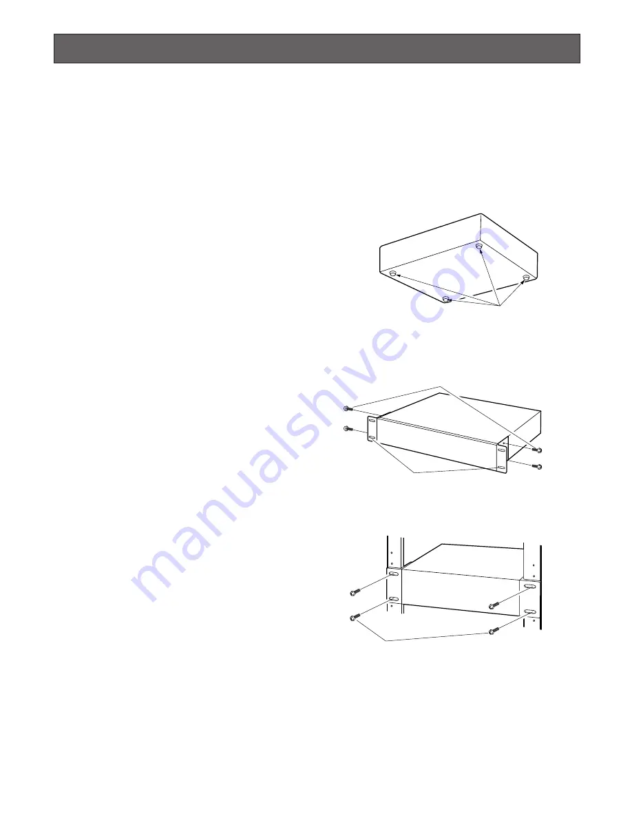
Rack Mounting

Important:

When installing the unit in the rack without turning the power of the unit off, activate the HDD safety mode. (Refer to page
34 for further information.)

Important 

• Do not install the unit above an appliance which generates heat such a power amplifier. When installing the unit below a

heat-generating appliance, install it below the appliance with a space equivalent to about 1 unit (44 mm {1.73"}) separating
them. 

• Keep the temperature in the rack below +45 °C {113 °F}. It is recommended to install cooling fans or equivalent equipment

to keep the temperature in the rack below +30° C {86 °F}.

1. Remove the four rubber feet from the bottom of the unit

using a flathead screwdriver. 

2. Place the provided rack mounting brackets on both

sides of the unit and tighten with the four provided
screws. 

3. Install the unit with the rack mounting brackets in the

rack by using four rack mounting screws.

Cautions:

• Make a space of 1U (44 mm {1.73"}) above and below

the unit for ventilation.

• Keep the temperature in a rack below 45 ˚C {113 ˚F}.
• Install a fan in the rack when the ambient temperature is

above 30 ˚C {86 ˚F}.

• Do not block the ventilation openings or slots on the

cover to prevent the unit from overheating.

Remove the rubber feet.

Mounting screws for rack mounting brackets 
(accessories)

 Rack mounting brackets (accessories)

Rack mounting screws

Содержание WJ-ND300A

Страница 1: ...read these instructions carefully and save this manual for future use ALARM ALARM SUSPENDED ERROR TIMER REC OPERATE 1 LINK ACT 2 HDD 1 HDD 2 HDD 3 ESC PULL Network Disc Recorder WJ ND300 300A SET HDD 4 Network Disk Recorder Installation Guide Model No WJ ND300A ...

Страница 2: ...t der folgenden Normen oder normativen Dokumenten übereinstimmt Gemäß den Bestimmungen der Richtlinie 73 23 EEC und 89 336 EEC Nous déclarons sous note seule responsabilité que le produit auquel se réfère la présente déclaration est conforme aux normes ou autres documents normatifs conformément aux dispositions des directives CEE 73 23 et CEE 89 336 FOR YOUR SAFETY PLEASE READ THE FOLLOWING TEXT C...

Страница 3: ...ING SAVED DATA FOR SOME REASON BECOMES PUBLIC OR IS USED FOR THE PURPOSE OTHER THAN SURVEILLANCE THIS PUBLICATION COULD INCLUDE TECHNICAL INAC CURACIES OR TYPOGRAPHICAL ERRORS CHANGES ARE ADDED TO THE INFORMATION HEREIN AT ANY TIME FOR THE IMPROVEMENTS OF THIS PUBLICATION AND OR THE CORRESPONDING PRODUCT S NOTE This equipment has been tested and found to com ply with the limits for a Class A digit...

Страница 4: ... your outlet consult an electrician for replacement of the obsolete outlet 10 Protect the power cord from being walked on or pinched particularly at plugs convenience receptacles and the point where they exit from the apparatus 11 Only use attachments accessories specified by the manufacturer 12 Use only with the cart stand tripod bracket or table specified by the manufacturer or sold with the app...

Страница 5: ...ion Unit 16 How to Use the Terminals of the ALARM CONTROL Connector 18 How to Use the Terminals of the ALARM Connector 22 How to Replace Hard Disk Drives 24 Turn On Off the Power of the Unit 27 Operating the Unit for the First Time 27 Turn on the Power of the Unit 27 Turn off the Power of the Unit 28 Operation Using the Buttons on the Front Panel 29 Check the Network Settings 30 Set the Network Se...

Страница 6: ...g their power on or off for around 30 sec onds When hard disk drive trouble occurs replace it immedi ately Consult your dealer for servicing When replacing the hard disk drives take notice of the following Protect the hard disk drives from static electricity Do not stack them or keep them upright Do not use an electric screwdriver to fix them Tightening torque Approx 0 49 N m 5 kgf cm Avoid rapid ...

Страница 7: ...certain period turn on the power of the unit approximately once a week and perform recording playback to prevent interferences with functions We recommend that you make a note of your settings and save them This will help when you are required to change the system configuration or when unexpected trouble or failure occurs Distributing copying disassembling reverse compil ing reverse engineering an...

Страница 8: ...load the latest Adobe Reader from the Adobe web site and install it WJ ND300A or ND300A shown in the illustrations used in these operating instructions indicate this unit or the WJ ND300A series About these Operating Instructions Network Security As you will use this product connected to a network your attention is called to the following security risks 1 Leakage or theft of information through th...

Страница 9: ...rding settings such as the recording rate by the schedule time Emergency Recording In the case of an emergency emergency recordings will be given a higher priority than other recording modes by operating an external switch External Timer Recording It is possible to perform recording automatically using an external timer Event Recording At an event occurrence such as when an alarm signal is supplie...

Страница 10: ...ication between a PC and the unit is established Blinks green when receiving data from a PC Front View o HDD Access Indicators HDD1 HDD2 HDD3 HDD4 Indicates the statuses of the hard disks Blinks green when the hard disk is accessed respec tively When using the RAID 5 function 1 these indicators will display the statuses as follows when an error occurs Lights red Indicates that the respective hard ...

Страница 11: ...f 0 i Signal Ground Terminal SIGNAL GND o Power Cord Inlet AC IN Connect the power cord to this inlet 10 100BASE T 2 1 EXT STORAGE SERIAL PC CAMERA AC IN ALARM CONTROL ALARM SIGNAL GND POWER ON OFF q w e r t y u i o q External Storage Connector EXT STORAGE Connect an optional extension unit WJ HDE300 series with this port w Client PC Port PC 10 100BASE T 2 Connect this unit to a network compatible...

Страница 12: ...rature in the rack below 30 C 86 F 1 Remove the four rubber feet from the bottom of the unit using a flathead screwdriver 2 Place the provided rack mounting brackets on both sides of the unit and tighten with the four provided screws 3 Install the unit with the rack mounting brackets in the rack by using four rack mounting screws Cautions Make a space of 1U 44 mm 1 73 above and below the unit for ...

Страница 13: ...ient PC port on the rear of the unit respectively as shown in the illustration below Images video signals from cameras will be supplied input to the CAMERA port and the supplied images will be transmitted output to PCs Important Do not connect PCs to a network to which the CAMERA port is connecting Otherwise transmission efficiency may be down Do not connect any camera to a network to which the cl...

Страница 14: ...ub connect them using a cross LAN cable Connection Example Connecting PCs using an ADSL line Note When using a router MPEG 4 images sometimes may not be displayed Refer to the network administrator for how to configure the settings of the router 10 100BASE T 2 1 EXT STORAGE SERIAL PC CAMERA AC IN ALARM CONTROL ALARM SIGNAL GND POWER ON OFF PC HUB HUB Network Cameras LAN Cable Not provided 10BASE T...

Страница 15: ... IN ALARM CONTROL ALARM SIGNAL GND POWER ON OFF 10 100BASE T 2 1 EXT STORAGE SERIAL PC CAMERA AC IN ALARM CONTROL ALARM SIGNAL GND POWER ON OFF First Unit PC PC HUB HUB LAN Cable Not provided 10BASE T 100BASE TX Category 5 Straight Network Cameras Second Unit HUB Network Cameras ...

Страница 16: ...at may cause recording failures or an unstable system AC IN SIGNAL GND 1 2 IN OUT EXT POWER IN OUT EXT 1 2 This unit Dedicated Cable Standard accessory of an extension unit Extension Unit WJ HDE300 Series Cable Clamp Cable Clamp Fixing screw Remove this screw from the unit and fix the cables with the cable clamp using the screw removed from the unit Fixing screw Remove this screw from the unit and...

Страница 17: ...the system with the extension units do not change the connection such as exchanging the unit numbers between the units Otherwise the unit numbers may not be distributed correctly and the units may not be recognized cor rectly Refer to page 35 for how to check the unit number of the connected extension unit 1 2 2 1 2 POWER AC IN SIGNAL GND 1 2 IN OUT EXT POWER AC IN SIGNAL GND 1 2 IN OUT EXT POWER ...

Страница 18: ...piration Open collector output 24 V DC max 100 mA 1 Alarm reset input 2 Emergency recording input 3 4 Signal ground 5 Alarm output for available disk space of the copy event recording area Signal output upon detection of a HDD error 6 HDD error output Signal output upon detection of a camera error 7 Camera error output Signal output upon detection of a unit error 8 Error output Signal output upon ...

Страница 19: ...DF Connection for the Auto Adjust Time function When Auto Adjust Time of Time Date of System on the SETUP MENU is set to MASTER Time Adjust Output becomes available and the clock of this unit can be applied to other units 19 Terminal block of other units Time adjust output Signal ground ALARM CONTROL Signal ground Sensor input Alarm input Alarm reset input Series recording input Time adjust input ...

Страница 20: ... is selected the auto time adjustment function works differently depending on the recording status as fol lows 1 When event recording is performed on any camera channel When no recording is being performed When manual recording is being performed When schedule recording is being performed The clock will be adjusted When event recording is being performed 1 When emergency recording is being perform...

Страница 21: ...em UPS Then the power supply to this unit can be suspended Connection of the control output When an alarm device such as a buzzer or a lamp is connected the signal output from Pin Nos 15 18 can be used to notify the status by sounding a buzzer or lighting a lamp The following example is of a connection with the HDD error output pin no 16 3 6 Alarming device Relay etc Signal ground HDD error output...

Страница 22: ... kΩ Alarm signal will be supplied at an event occurrence Open collector output 24 V DC max 100 mA Event action will be performed according to the setting Non voltage make contact input 5 V pull up 150 kΩ Alarm signal will be supplied at an event occurrence Open collector output 24 V DC max 100 mA Remarks w Alarm input 2 e Alarm input 3 r Alarm input 4 t Alarm input 5 y Alarm input 6 u Alarm input ...

Страница 23: ...recording input Alarm output for available disk space of the copy event recording area HDD error output Camera error output Error output Outage processing end output Time adjustment I O Alarm suspend input Outage detection input External recording mode changeover Active time 100 ms or more The set time on the SETUP MENU Until the network error is cleared or until the ALARM RESET button on the oper...

Страница 24: ... and the front panel while the HDD status indicators are still lit or until 30 seconds have passed since the HDD status indicators went off Protect the hard disk drives from static electricity Do not stack them or keep them upright Do not use an electric screwdriver to secure them Tightening torque 0 49 N m 5 kgf cm Avoid rapid changes in the temperature and humidity to prevent condensation Accept...

Страница 25: ...mper connectors to the master side Refer to the instruction manual attached to the hard disk drive for details 8 Mount the hard disk drives on the extension unit Use the screws that had been removed in Step 4 Do not use an electric screwdriver for impact preven tion Tightening torque 0 784 N m 8 kgf cm Important The identification numbers of the built in hard disk dri ves are assigned as shown bel...

Страница 26: ...e hard disk drive of the extension unit it is necessary to detach the front panel in the same way as described above Refer to the operating instructions for descriptions of how to replace the hard disk drive of the extension unit Important When detaching the front panel confirm that the OPER ATE indicator on the front panel is off m After completing the HDD replacement attach the cable to the fron...

Страница 27: ...series turn on the power of this unit after turning on the power of all extension units 27 Turn On Off the Power of the Unit Operating the Unit for the First Time Important When connecting an optional extension unit WJ HDE300 series turn on the power of the extension unit before turning on this unit 1 Turn on the POWER switch The OPERATE indicator will light and the system check checking the syste...

Страница 28: ...back recorded pictures stop the play back Click the button displayed when the HDD tab is selected Refer to the Setup Instructions PDF for details 2 Turn off the POWER switch on the rear of the unit Turn off the power of the unit after confirming that all the HDD access indicators are off Important Detach the plug from the outlet if not operating the unit for a length of time When the unit has not ...

Страница 29: ...ssible to check each network setting such as the IP address or the subnet mask Refer to page 30 for details IP address setup display The network settings can be set with this display Press the SET button on the front panel while displaying this display It is possible to set each network setting such as the IP address or the subnet mask Refer to page 31 for details Key lock mode display It is possi...

Страница 30: ... It is possible to check the following network settings DHCP IP address Subnet mask Gateway 1 HTTP port 1 To check each setting shift the display as follows Note To change the port number PT press the arrows button A or B Camera port PT 1 Client PC port PT 2 Maintenance port PT 3 1 The settings of Gateway and HTTP port can be checked by displaying the client PC port PT 2 C Arrows buttons D SET ESC...

Страница 31: ... ESC ESC ESC C Arrows buttons D 1 Move the underscore mark below the number to be edited The underscore mark will move below the number by pressing the SET button while the underscore mark is displayed below the indication 2 Enter the desired values Move the underscore mark Arrows button A and B Enter values Arrows button C and D Important Network settings for each port IP address etc should be on...

Страница 32: ...ote Default password 12345 Set the HDD Mode The following HDD modes are available for maintenance RAID 5 mode settings RAID5 Set to the RAID 5 setting Single mode settings SINGLE Release the RAID 5 mode and set to the single mode HDD recovery RECOVERY Perform the HDD recovery after replacing the HDD when one of the RAID disk failed RAID board initialization INIT Initialize the RAID board It is nec...

Страница 33: ...automatically and each menu item will be carried out when the SET button is pressed after moving the underscore mark below YES using the arrows button A or B The unit will restart when RAID5 SINGLE RECOVERY or INIT is carried out The power of all HDDs will be turned off when the HDD safety mode is activated It takes approx 30 sec until the power is turned off When the power of the HDDs is turned o...

Страница 34: ... 2 Reboot the unit Press the SET button after selecting REBOOT using the arrows button A and B when the REBOOT PANEL OFF indi cation is displayed The unit will restart 3 Detach the front panel Press the SET button after selecting PANEL OFF using the arrows button A and B when the REBOOT PANEL OFF indication is displayed The OPERATE indicator and the LCD will go off Important Detach the front panel...

Страница 35: ...utton is pressed while the EXT Unit 1 indication is displayed the HDD access indicators HDD1 HDD4 of the extension unit with unit number 1 will light red for around 5 seconds The displayed unit number can be shifted to the other unit number using the arrows button C or D 3 Quit the unit number check Display Reboot by pressing the arrows button C or D and then press the SET button The unit will res...

Страница 36: ...t the unit manually as follow Press the SET button while displaying the REBOOT display The message ACCEPT will be displayed When the SET button is pressed after moving the underscore mark below YES using the arrows button A or B the unit will reboot SET ...

Страница 37: ...t acti vated Check item Remedy Page Problem 22 18 22 The error indicator blinks orange The unit stops because of the thermal error The HDD access indicator lights blinks red 6 The respective HDD is failed in the RAID 5 mode The indicator respective to the HDD that failed first will light red and the indicators for the other failed HDD will blink red Aren t the fans on the rear or the ventilation s...

Страница 38: ...en bent or stretched Check item Remedy Problem Problem Check item Remedy The HDD access indicator lights red and orange The system error occurred Refer to the dealer The system error status will be displayed with the HDD indi cators as follows 8 Red 9 Orange 9 8 8 8 Hardware malfunction 8 9 8 8 Hardware malfunction 9 9 8 8 Hardware malfunction 8 8 9 8 Hardware malfunction 9 8 9 8 Hardware malfunct...

Страница 39: ...o 45 C 41 F 113 F 5 90 non condensing 2 000 m 6 562 feet above sea level 420 mm W x 88 mm H x 350 mm D 16 9 16 W x 3 7 16 H x 13 3 4 D excluding rubber feet and projections 8 3 kg 18 3 lbs Emergency recording input 1 Alarm output for available disk space of the copy event recording area 2 HDD error output 2 Camera error out put 2 Error output 2 Power outage recovery completion output 1 Time adjust...

Страница 40: ...c equipment please contact your dealer or supplier for further information Information on Disposal in other Countries outside the European Union This symbol is only valid in the European Union If you wish to discard this product please contact your local authorities or dealer and ask for the correct method of disposal For U S Canadian and Puerto Rican fields Panasonic System Solutions Company Unit...

Отзывы: