background image

31

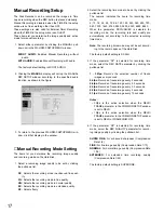
2. Select a sensitivity mode for a camera (1CH) by click-

ing the pulldown list.

OFF:

Disables the motion detector function.

LOW:

Selects lower sensitivity.

MID:

Selects normal sensitivity.

HIGH:

Selects higher sensitivity.

The factory default setting is OFF.

3. Repeat the above step to designate the other camera

channels.

4. When satisfied with all of the above steps, click the

[SET]

button to execute the selections.

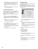
5. If the parameter is set to something other than OFF in

step 2, select the corresponding channel in the VMD
AREA SETUP PAGE by clicking the button.
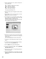
The alarm detecting area setup window as shown in the
figure will appear on the display screen.

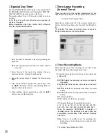
6. Drag the mouse pointer on the screen from the starting

point to the ending point to determine the rectangular
detecting area.
Up to four detecting areas can be set on the screen.

7. To assign an other detecting area, repeat the above

step 6.

8. To delete the area, click the rectangle to be delete on

the screen, then click the 

[DELETE]

button.

9. Click the 

[SET]

button to execute the selections.

10. To return to the previous window, click the 

[RETURN

VMD AREA SETUP]

button.

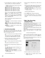
11. Repeat the above steps 5 to 10 to set the detector func-

tion for other cameras.

12. Click the ALARM SETUP in the underneath of the VMD

AREA SETUP window to return to the previous ALARM
SETUP menu.

Содержание WJ-HDB502

Страница 1: ...Model No WJ HDB502 Network Board User s Manual Before attempting to connect or operate this product please read these instructions carefully and save this manual for future use ...

Страница 2: ...imer 22 Emergency Recording Time Lapse Recording 23 MULTIPLEXER SETUP 25 Multiplexer Setup 25 Power on Status Setup 25 Secret View Setting 25 Sequence Setup 26 Sequence Setup Multiscreen Monitor 26 Sequence Setup Spot Monitor 27 Multi Live Sequence Setting Multiscreen Monitor 27 Quad Pattern Setup 28 Spot Live Sequence Setting Spot Monitor 28 ALARM SETUP 29 Alarm Setup 29 Alarm Port Setting 30 Vid...

Страница 3: ...ng minimum requirements to set up the board OS One of the following Operating Systems Windows95 Windows98 WindowsNT Browser Netscape Communicator 4 04 or later Internet Explorer 4 01 SP or later Display 800 x 600 pixels or more Trademarks Adobe and Acrobat Reader are trademarks of Adobe Systems Incorporated Netscape and Netscape Communicator are registered trademarks of Netscape Communications Cor...

Страница 4: ...der WJ HD FS 16 Personal Computer Ethernet Cross Cable Super Dynamic Hub REMOTO TIMER OPERATE FULL HDD SEQUENCE SET LOCK ALARM ALARM RESET ALARM SUSPEND MULTISCREEN SELECT SET UP ESC GROUP SELECT SPOT MULTISCREEN DAYLIGHT SAVINGS EL ZOOM COPY REC PREVIEW INDEX STOP PLAY PAUSE REC FWD REV ALARM SEARCH DISPLAY REC STOP 1 2 3 4 13 14 15 16 9 10 11 12 5 6 7 8 Digital Disk Recorder WJ HD FS 16 Digital ...

Страница 5: ... Gateway 192 168 0 1 For a client PC to access WJ HDB502 factory default set tings set the IP address of the PC to 192 168 0 means any number from 2 to 254 except 10 q Power up the client PC w Change the PC s TCP IP to match the factory default settings of the WJ HD500 If your PC s OS is Windows95 or Windows98 proceed as follows 1 Click the Start button point to settings and then click Control Pan...

Страница 6: ...rs for domains beginning with specify 192 168 0 10 Main Page and Control Window Start the WWW browser of your PC in the URL Uniform Resource Locators type http 192 168 0 10 or IP Address set for WJ HD500 The browser displays the MAIN CONTROL PANEL of the WJ HDB502 s homepage shown in the figure Note Specify http 192 168 0 10 when a client PC is connected alone Specify http IP address previously se...

Страница 7: ...7 WJ HDB502 BOARD SETUP ...

Страница 8: ...ail address for alarm notices function USER Specifies users and access levels HOST Specifies hosts and access levels PS Data Specifies communication parameters for using PS Data mode 4 To return to the previous MAIN CONTROL PANEL click the MAIN MENU button on the window Network Setup The items in the window let you set the communication parameters of the WJ HDB502 Network Board Changing the parame...

Страница 9: ... 1 4FRAME Lower resolution 360 x 240 image The factory default setting is FIELD 3 Select an image quality for the images on the display by clicking the pulldown list The factory default setting is SUPER FINE 4 Select a bandwidth transmission speed from the board to the network by clicking from the pulldown list The factory default setting is UNLIMITED 5 Click the SET REBOOT button to execute the s...

Страница 10: ... the activated alarm q Enter a mail address to notify the alarm w Click the SET button to register the entered address e To register other destination repeat the procedure q and w 2 To delete the destination from the list q Select a mail address by clicking the pulldown list w Click the DELETE button to execute the deletion from the list User Setup Clicking the USER button in the window the USER S...

Страница 11: ...licking the button The access level is defined as shown below Refer to Access Authorization for further details 1 ADMIN Enables all controls and setup 2 PLAY Enables monitoring live images and playing back the recorded images 3 USER Enables only monitoring live images 2 Click the SET button to register the host 3 Repeat the above steps 1 and 2 to register the other hosts Host Deletion To delete a ...

Страница 12: ...ication by clicking the button The factory default setting is NONE 6 Select one of the waiting time in milli seconds ms to retry for RS 485 communication by clicking the pull down list The factory default setting is OFF no retry 7 Click the SET button to execute the selections 8 To return to the previous NETWORK window click the NETWORK display in the underneath of the window OFF 100 200 400 1000 ...

Страница 13: ...13 WJ HD500 SETUP ...

Страница 14: ...dmin Password nil not required Programming Setup Window As shown in the figure the WJ HD500 SETUP MENU win dow has eight main submenus Seven of these are further divided into additional submenus The display underlined indicates that the item has a sub menu for more detailed setups Timer Setting The timer recording mode is triggered by the internal or an external timer This item lets you enable or ...

Страница 15: ...ting is COLOR STD Other Recording Settings 1 Select either ON or OFF by clicking the button The item lets you enable or disable recording of the camera and group titles with the image on the Hard Disk ON Enables recording of the titles on the Hard Disk OFF Disables recording of the titles on the Hard Disk The factory default setting is OFF 2 Select either ON or OFF by clicking the button The item ...

Страница 16: ...t a group number 1 to 4 to be assigned for a camera by clicking the pulldown list in the GROUP col umn The factory default settings is 1 2 Repeat the above step to assign the group number for other cameras 3 When all camera assignments are completed click the SET button to execute the selections 4 To return to the previous COMMON SETUP window click the HD500 SETUP MENU display in the window Group ...

Страница 17: ... be set by clicking the pulldown list The numeric indicates the hours for recording time mode 2 12 18 24 48 72 96 120 180 240 360 480 720 960 1200 1440 2160 2880 3600 4320 6480 8640 When the parameter SF FQ NQ EX is selected for recording mode the recording rate and quality are automatically set according to the selected recording time mode Note The recording time mode may not be set accord ing to...

Страница 18: ...ular images that have activated the alarm The factory default setting is OFF 6 Click the SET button to execute the selection 7 To return to the previous WJ HD500 SETUP MENU win dow click that display in the window Timer Recording Setup The Disk Recorder can record the images triggered by the internal timer The internal timer comprises four event times common to the recording groups and is programm...

Страница 19: ...reviously edit the assigned program number window as described follows 3 Click the SET button to execute the selections Program Timer The described below let you determine the program timer schedule and recording mode Click the More button of the assigned program number PROG1 in the TIMER REC SETUP window the assigned program number window as shown in the figure will appear on the display screen 1...

Страница 20: ... Recording assigned in the program number window Continued from Program Timer Select the recording mode T L in the program number win dow by clicking the pulldown list then click the More but ton The selected Time Lapse Recording window as shown in the figure will appear on the display screen Timer Recording Mode These items let you set the recording mode in Time Lapse Recording with the internal ...

Страница 21: ... menu 4 Select the alarm recording duration by clicking the pull down list 10S 6M Enables alarm recording for between 10 sec onds and 6 minutes MANUAL Enables alarm recording while the alarm sig nal is received from the ALARM port CONTINUE Enables alarm recording until the REC STOP is pressed The factory default setting is 10S 5 Select an alarm recording pattern by clicking the pull down list OFF ...

Страница 22: ...ding pattern for post recording by click ing the pulldown list OFF Records the images assigned to group inputs including the one that has activated the alarm the same as pre recording ALM ONLY Records the particular image that has acti vated the alarm The factory default setting is OFF 6 Click the SET button to execute the selections 7 Click the PROG SETUP display in the underneath of the window t...

Страница 23: ...ow The selected EMERGENCY REC SETUP window as shown in the figure will appear on the display 3 Select a recording time mode by clicking the pulldown list SF H Selects the recording time mode in enhanced fine quality FQ H Selects the recording time mode in fine quali ty NQ H Selects the recording time mode in normal quality EX H Selects the recording time mode in extended time quality SP Freely sel...

Страница 24: ...Select the recording duration by clicking the pulldown list 10S 6M Enables recording for between 10 seconds and 6 minutes MANUAL Enables recording while the input signal is received from the CONTROL port CONTINUE Enables recording until the REC STOP but ton of the Disk Recorder is pressed The factory default setting is 10S 6 Click the SET button to execute the selections 7 Click the HD500 SETUP ME...

Страница 25: ...itor QUAD 4A to QUAD 4D Selects an assigned quad dis play in spot mode QUAD SEQ Selects a sequence pattern programmed in the Live Sequence Multiscreen Monitor MULTIPLEXER SETUP 7 to 16SCREEN Selects a display with the assigned segment The factory default setting is QUAD 4A 2 Select a display pattern on the Spot Monitor by clicking the pulldown list 1 16 Selects an assigned camera image in single s...

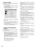
Страница 26: ...ts you select between internal and external control for advancing the sequence on the Multiscreen Monitor INT Advances a sequence by the Dwell Time that was programmed in the MULTI LIVE SEQ SETUP win dow EXT Advances a sequence by the input from pin 5 of the ALARM port on the rear of the Disk Recorder The factory default setting is INT 3 Select either QUAD or MULTI GROUP display mode to be run on ...

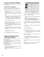
Страница 27: ...un on the Multiscreen Monitor The items shown below let you program the sequence to run on the Multiscreen Monitor Multi Live Sequence is a series of 16 steps assigned to the Multiscreen Monitor The sequence steps can be combined with four screen segments quad display 1 Click the MULTI LIVE SEQ SETUP in the underneath of the SEQUENCE SETUP window The window shown in the figure will appear on the d...

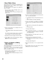
Страница 28: ...he Spot Monitor This sequence can be run on the Multiscreen Monitor by operating the buttons 1 Click the SPOT LIVE SEQ SETUP in the underneath of the SEQUENCE SETUP window The window shown in the figure will appear on the dis play screen 2 Select a camera to be displayed in the CAM column for step 1 by pressing the keyboard 1 16 Displays the image of the selected camera num ber Disables display an...

Страница 29: ...cts an alarm output between 1 second and 5 minutes EXT Alarm output continues until the ALARM RESET button is pressed or the external alarm recover sig nal is received from the ALARM port on the rear of the Disk Recorder 4 If the 1 30 SEC is selected for the parameter select a value by pressing the keyboard The factory default setting is 2 SEC 5 Select the ringing duration by clicking the pulldown...

Страница 30: ...lect a camera number CAM1 CAM16 correspond ing to the input in the CAMERA editing area by clicking the pulldown list 4 Select the type of contact to meet the system require ment in the INPUT editing area by clicking the pulldown list Normally Open Accepts alarm input from Normally Open contacts Normally Close Accepts alarm input from Normally Closed contacts The factory default setting is Normally...

Страница 31: ... The alarm detecting area setup window as shown in the figure will appear on the display screen 6 Drag the mouse pointer on the screen from the starting point to the ending point to determine the rectangular detecting area Up to four detecting areas can be set on the screen 7 To assign an other detecting area repeat the above step 6 8 To delete the area click the rectangle to be delete on the scre...

Страница 32: ...p title on the monitor screen The factory default setting is ON 3 Select either ON or OFF to enable or disable the status display on the Multiscreen Monitor by clicking the but ton ON Enables the status display on the monitor screen OFF Disables the status display on the monitor screen The factory default setting is ON 4 Select the mode or color for the display of borders by clicking the pulldown ...

Страница 33: ...d in the lower left corner of the monitor screen R LOWER Placed in the lower right corner of the moni tor screen CENTER Placed in the center of the monitor screen The factory default setting is R LOWER Camera Title Setup This item lets you edit the camera title to be displayed on the monitor screens Up to 8 alphanumeric characters can be displayed on the monitor screen 1 Click the CAMERA TITLE SET...

Страница 34: ...own list The factory default setting is 9600 bps 3 Select NONE EVEN or ODD for parity check by clicking the button The factory default setting is NONE 4 Select either 1 or 2 for the number of stop bits by click ing the button The factory default setting is 1 bit 5 Select OFF 100 200 400 1 000 ms for the wait time by clicking the pulldown list The item lets you set the waiting time in milliseconds ...

Страница 35: ...splay 2 Select a unit address number of the Disk Recorder to be used for RS 232C communication by pressing the keyboard Select a parameter value between 001 and 099 The factory default setting is 001 3 Select a transmission speed Baud Rate shown below by clicking the pulldown list The factory default setting is 9600 bps 4 Select either 7 or 8 for the number of data bits by click ing the button The...

Страница 36: ... or disable time adjustment by the input output from the CONTROL port OFF Disables the time adjustment from the CONTROL port MASTER Enables the time adjustment output from the CONTROL port to set time for connected external device SLAVE Enables to set the time of this recorder by the input from the CONTROL port The factory default setting is OFF 2 If the parameter is set to something other than OF...

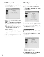
Страница 37: ...evious SYSTEM SETUP window click the SYSTEM SETUP display in the window Error Report There are 100 error records stored in chronological order in 10 pages of tables 1 Click the ERROR REPORT in the SYSTEM SETUP win dow The ERROR REPORT table as shown in the figure will appear on the display 2 Clicking the NEXT 10 or PREV 10 display in the window will select the next or previous page of the tables 3...

Страница 38: ...39 SYSTEM OPERATIONS ...

Страница 39: ...e device control commands are given top priority in the execution chain there is no priority attached to the access level It is possible to designate more than one network administrator and to change designated administrators Administrator Level 1 Monitoring live images Input select and camera control Playback recorded images Recording live images Alarm reset operation Access to and setup of the W...

Страница 40: ...password consisting of up to 16 alphanumeric characters case sensitive Select mark any of access levels 1 to 3 Check Operation Level Host Level Authorization Process Operation will be Accepted Operation will be Denied User Level Authorization Process Operation Request OK NG NG OK WJ HD500 Authorized Functions ...

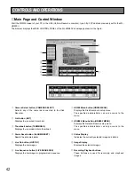
Страница 41: ... button ALARM RESET Resets the activated alarm t Live On button LIVE ON Displays the live images y Live Sequence button LIVE SEQUENCE Displays the live images in programmed sequence q w r t u y e 1 u HD500 Menu button HD500 MENU Displays the Disk Recorder s setup menu The specified administrator can only access to the menu i HDB502 Menu button HDB502 MENU Displays the Network Board s setup menu Th...

Страница 42: ...s can be recorded as same as Manual Recording in Time Lapse Recording The recording operation is only available the users set access level 1 1 Click the REC button on the panel When the user name and password dialog box appears enter the user name and password to log in The Manual Recording will start 2 To quite the recording click the REC STOP button on the panel Playing Back Recorded Images The ...

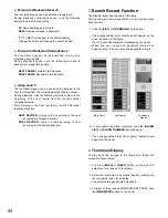
Страница 43: ...inning of the next recording in a forward direction PREV RECORD Jumps to the beginning of next recording in a backward direction Search Record Function The Disk Recorder has two search functions The procedures below describe how to search and play back records 1 Click the LIST or THUMBNAIL on the panel The corresponding list or thumbnail will appear on the panel as shown in the figure Up to 16 lis...

Страница 44: ...nel Alarm Reset Function The Alarm Function activates the warning alarm status when the externally connected alarm sensor is turned on or an installed Video Motion Detector optional is activated 1 When an alarm is activated in the system ALM will appear on the Status Display of the MAIN CONTROL PANEL 2 To return to the normal state previously click the ALARM RESET button on the panel When the user...

Страница 45: ...the AUTO PANI buttons to control the auto panning function ON Activates auto panning function OFF Deactivates auto panning function 6 Clicking anywhere on the live image moves the camera optional up and down or to the right and left The camera pan tilt angle increases or decreases as the point clicked moves further or closer to the image center To move the camera continuously click the image repea...

Страница 46: ...onic Security and Digital Imaging Systems Company A Division of Matsushita Electric Corporation of America Executive Office One Panasonic Way 3E 7 Secaucus New Jersey 07094 Regional Offices Northeast One Panasonic Way Secaucus NJ 07094 201 348 7303 Southern 1225 Northbrook Parkway Suite 1 160 Suwanee GA 30024 770 338 6838 Midwest 1707 North Randall Road Elgin IL 60123 847 468 5211 Western 6550 Kat...

Отзывы: