


1 Safety Precautions
1.1.
General Guidelines
1. When conducting repairs and servicing, do not attempt to modify the equipment, its parts or its materials.
2. When wiring units (with cables, flexible cables or lead wires) are supplied as repair parts and only one wire or some of the
wires have been broken or disconnected, do not attempt to repair or re-wire the units. Replace the entire wiring unit instead.
3. When conducting repairs and servicing, do not twist the Faston connectors but plug them straight in or unplug them straight
out.
4. When servicing, observe the original lead dress. If a short circuit is found, replace all parts which have been overheated or
damaged by the short circuit.
5. After servicing, see to it that all the protective devices such as insulation barriers, insulation papers shields are properly
installed.
6. After servicing, make the following leakage current checks to prevent the customer from being exposed to shock hazards.
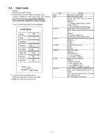
1.1.1.
Leakage Current Cold Check
1. Unplug the AC cord and connect a jumper between the
two prongs on the plug.
2. Measure the resistance value, with an ohmmeter,
between the jumpered AC plug and each exposed metal
lic cabinet part on the equipment such as screwheads,
connectors, control shafts, etc. When the exposed metal
lic part has a return path to the chassis, the reading
should be between 1Mohm and 5.2Mohm.
When the exposed metal does not have a return path to
the chassis, the reading must be
O O .
1.1.2.
Leakage Current Hot Check (See
Figure 1.)
1. Plug the AC cord directly into the AC outlet. Do not use
an isolation transformer for this check.
2. Connect a 1.5kohm, 10 watts resistor, in parallel with a
0.15|iF capacitors, between each exposed metallic part
on the set and a good earth ground such as a water pipe,
as shown in Figure 1.
3. Use an AC voltmeter, with 1000 ohms/volt or more sensi
tivity, to measure the potential across the resistor.
4. Check each exposed metallic part, and measure the volt
age at each point.
5. Reverse the AC plug in the AC outlet and repeat each of
the above measurements.
6. The potential at any point should not exceed 0.75 volts
RMS. A leakage current tester (Simpson Model 229 or
equivalent) may be used to make the hot checks, leakage
current must not exceed 1/2 milliamp. In case a measure
ment is outside of the limits specified, there is a possibility
of a shock hazard, and the equipment should be repaired
and rechecked before it is returned to the customer.
Figure 1
3
Содержание Viera TC-P50C2
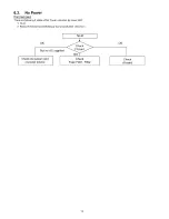
Страница 19: ...6 4 No Picture Input only y v h a t s lnPut 0Г 1 У Signal 19 ...
Страница 32: ...32 ...
Страница 33: ...10 Block Diagram 10 1 Main Block Diagram A D IG ITAL SIG NAL PROCESSO R 33 ...
Страница 34: ...10 2 Block 1 4 Diagram ...
Страница 35: ...10 3 Block 2 4 Diagram A D IG ITAL SIG N AL PROCESSO R 35 ...
Страница 36: ...10 4 Block 3 4 Diagram I p PO W ER SUPPLY 36 ...
Страница 37: ...10 5 Block 4 4 Diagram s C s c a n d r iv e SS SU STAIN DRIVE PLASMA PANEL PANEL SUSIAIN ELECTRODE 37 ...
Страница 38: ...38 ...
Страница 40: ...11 3 Wiring 2 40 ...
Страница 41: ...11 4 Wiring 3 41 ...
Страница 42: ...42 ...
Страница 47: ...14 15 16 17 18 45 ...
Страница 49: ...24 25 26 27 ...
Страница 50: ...12 5 А Board 4 14 Schematic Diagram A A B O A R D TXN A1 LNUUS 4 14 P O W E R SU P P LY 28 29 30 31 32 47 ...
Страница 52: ...12 6 А Board 5 14 Schematic Diagram A A B O A R D TXN A1 LNUUS 5 14 A V S W PC M O D EL TO 1 14 r 37 38 39 40 ...
Страница 56: ...12 9 A Board 8 14 Schematic Diagram A A B O A R D TXN A 1LN U U S 8 14 HDMI 64 65 66 67 68 69 70 71 72 51 ...
Страница 57: ...12 10 A Board 9 14 Schematic Diagram 52 ...
Страница 59: ...12 12 A Board 11 14 Schematic Diagram A 91 92 93 94 95 96 97 98 99 TO 1 6 10 14 54 0 0 0 ...
Страница 60: ...12 13 A Board 12 14 Schematic Diagram 100 1 101 1 102 1 103 1 104 1 105 1 106 1 107 1 108 55 ...
Страница 62: ...12 15 A Board 14 14 Schematic Diagram Ш 222 TO A34 C2 BOARD C21 118 119 120 121 122 123 124 126 126 57 ...
Страница 63: ...12 16 C1 Board Schematic Diagram D A C1 B O A R D T X N C 11LNUU 58 ...
Страница 64: ...1 I Н X I I H I I I 6 7 8 9 ...
Страница 65: ...12 17 C2 Board Schematic Diagram A C D B E F i 2 3 4 8 9 5 59 ...
Страница 66: ...12 18 SC Board 1 4 Schematic Diagram A C D A S C BO AR D TX N S C 1LN U U 1 4 TO B E F 1 2 3 4 6 8 9 5 7 60 ...
Страница 67: ...12 19 SC Board 2 4 Schematic Diagram 10 11 12 13 14 15 16 17 18 61 ...
Страница 68: ...12 20 SC Board 3 4 Schematic Diagram A S C BO AR D TXN S C 1LN U U 3 4 19 20 21 22 23 24 25 26 27 62 ...
Страница 69: ...12 21 SC Board 4 4 Schematic Diagram A S C BO AR D TXN S C 1LN U U 4 4 28 29 30 31 32 33 34 35 36 63 ...
Страница 70: ...12 22 SS Board 1 2 Schematic Diagram A C D A B E F 6 5 7 64 ...
Страница 73: ...S BOARD FOIL SIDE TXN S1EQUUM S BOARD COMPONENT SIDE TXN S1EQUUM F I G I H ...
Страница 74: ...Z9 9 SnnNI l V NXl aais nod aavoa v pjeog v Z ZV ...
Страница 75: ...68 ...
Страница 77: ...13 4 C2 Board 6 3 C2 BOARD COMPONENT SIDE TXNC21LNUU 70 ...
Страница 78: ...13 5 SC Board 71 ...
Страница 79: ...SC BOARD COMPONENT SIDE TXNSC1LNUU G 6 5 4 3 2 1 E F H 72 ...
Страница 80: ...13 6 SS Board 6 5 4 SS BOARD FOIL SIDE TXNSS1LNUU ...
Страница 81: ...1 I F I G I H 73 ...
Страница 82: ...6 5 4 SS BOARD COMPONENT SIDE TXNSS1LNUU A В С D ...
Страница 83: ...74 ...
Страница 85: ...14 1 2 Exploded View 2 76 ...
Страница 86: ...14 1 3 Accessories 77 ...


