172
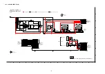
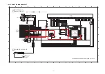
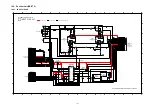
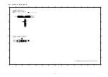
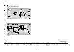
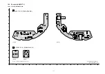
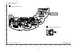
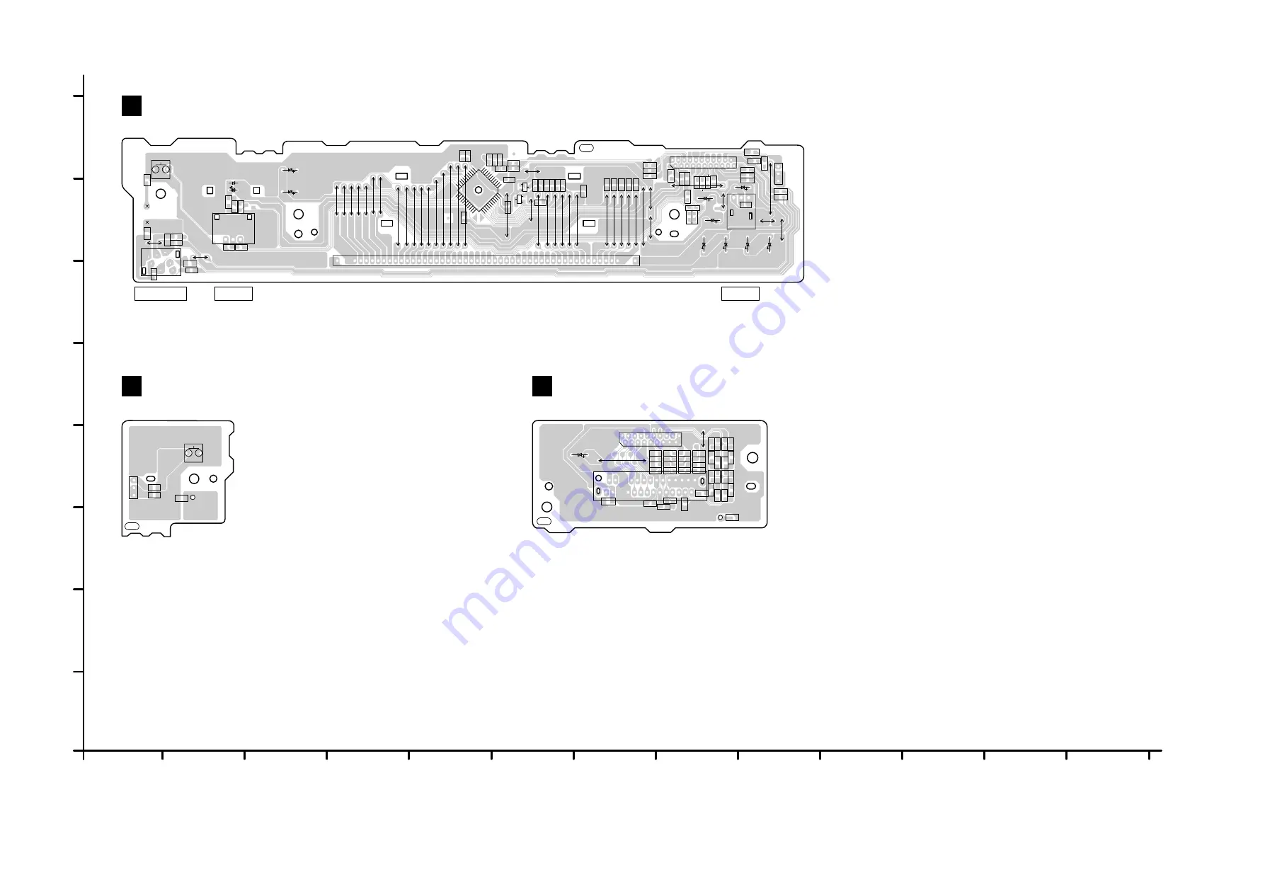
19.1.4. PANEL / POWER SW / WIRELESS TX P.C.B.
1
1
2
3
4
5
6
7
8
9
A
B
C
D
E
F
G
H
10
1
12
13
D
F
E
NOTE: " * " REF IS FOR INDICATION ONLY.
PANEL P.C.B. (REP4526FB)
WIRELESS ADAPTER P.C.B. (REP4526FC)
POWER SW P.C.B. (REP4526FD)
SC-ZT2EE/GS(SU-ZT2EE/GS)
PANEL / POWER SW / WIRELESS ADAPTER P.C.B.
3348BB-3
3348BB-3
3348BC-3
3348BC-3
3348BD-3
3348BD-3
C4602
C4603
C4604
C4607
C4608
C461
1
C4616
C4621
C4622
C4623
C4624
C4625
C4626
C4627
C4628
C4629
C4630
C4631
C4632
C4634
C4635
C4636
C4641
(SELECTOR)
C4651
C4652
C4653
D4602
IC4601
L4611
L4612
L4613
L4614
LB4741
LB4742
LB4743
LB4744
LB4745
LB4746
LB4747
LB4748
LB4749
LB4750
LB4751
LB4752
LB4753
LB4754
LB4755
LB4756
LB4757
LB4758
LB4759
LB4760
LB4761
LB4762
QR4602
QR4603
R4601
R4602
R4603
R4604
R4605
R4607
R4608
R4609
C4605
C4606
C4609
C4610
C4612
C4613
C4614
C4615
C4633
CN4611
D4601
FL4601
JK4611
JW4602*
K4601
S4602
VR4601
Z4601
W519
W518
W517
W516
W515
W514
W513
W512
W51
1
W503
W509
W504
W523
W524
W525
W526
W527
W528
W529
W530
W531
W532
W520
W540
W537
W538
W535
W534
W533
W536
W522
W521
W510
W502
W501
W505
W506
W507
W508
W539
TP4601
TP4611
C4701
C4702
C4703
C4704
C4705
C4706
C4707
C4708
C4709
C4710
C4711
C4712
C4713
C4714
C4715
C4716
C4719
C4720
LB4721
LB4722
LB4723
LB4724
R4701
R4702
R4703
R4704
R4705
R4706
R4707
R4708
R4709
R4710
R4711
R4712
R4713
R4714
R4715
R4716
C4718
CN4702
CN4703
W602
C4721
W601
TP4701*
JW4612*
S4601
TP4612*
C4654
LB4766
(POWER)
LB4767
VOLUME
HEADPHONE
SENSOR
(TO DIGITAL TRANSMITTER)
PbF
PbF
PbF
B
C
E
B
C
E
2
1
4
3
6
5
8
7
10
9
12
11
14
13
16
15
18
17
20
19 21
22
1
45
10
15
20
49
52
25
30
35
4
5
40
7
6
5
4
3
2
1
1
2
3
1
2
3
1
2
3
1
5
11
12
17
22
23
28
33
34
39
44
2
1
4
3
6
5
8
7
10
9
12
11
14
13
16
15 17
18
19
22
21
20
19
18
17
16
15
14
13
12
11
10
9
8
7
6
5
4
3
2
1
23
24
25
26
1
2
3
Содержание VIERA Link SB-ZT2EE
Страница 10: ...10 5 Location of Controls and Components 5 1 Main Unit SU ZT2 ...
Страница 11: ...11 5 2 Speaker Unit SB ZT2 5 3 Remote Control ...
Страница 12: ...12 6 Installation ...
Страница 13: ...13 6 1 Basic Connections 6 1 1 Connecting equipment with HDMI terminal TV DVD recorder etc ...
Страница 14: ...14 6 1 2 Connecting equipment without HDMI terminal DVD player VCR etc ...
Страница 15: ...15 6 1 3 Connecting STB etc and audio terminals DVD player etc ...
Страница 16: ...16 6 1 4 Other connections ...
Страница 17: ...17 6 2 AC power supply connection ...
Страница 18: ...18 7 Speaker setting SB ZT2 7 1 Setting the speakers Front and Surround speakers ...
Страница 19: ...19 ...
Страница 20: ...20 7 2 Setting surround speakers ...
Страница 28: ...28 9 2 2 Speaker Unit SB ZT2 ...
Страница 29: ...29 9 2 3 Speaker Unit SB ZT2 Wireless Link ...
Страница 30: ...30 ...
Страница 32: ...32 ...
Страница 33: ...33 10 1 Main Parts Location Diagram 10 1 1 Main Unit SU ZT2 ...
Страница 34: ...34 10 1 2 Speaker Unit SB ZT2 ...
Страница 36: ...36 10 2 2 Speaker Unit SB ZT2 ...
Страница 49: ...49 Step 4 Remove the Weight ...
Страница 50: ...50 Step 5 Remove 10 screws ...
Страница 54: ...54 Step 11 Remove 2 screws Step 12 Lift up to remove Arm Cover A ...
Страница 56: ...56 Step 14 Tilt the Woofer Block in order as arrows shown to detach it from the Tweeter Block ...
Страница 57: ...57 10 4 2 Disassembly of Middle Cabinet Assembly Refer to Disassembly of Woofer Block Step 1 Remove 7 screws ...
Страница 67: ...67 Step 3 Remove the heatsink with the IC5701 ...
Страница 68: ...68 Step 4 Remove 1 screw Step 5 Remove IC5701 from the heatsink ...
Страница 70: ...70 Step 4 Place the heatsink with the IC5701 onto the SMPS P C B ...
Страница 73: ...73 Step 2 Desolder pins of Diode D5802 on the solder side of SMPS P C B Step 3 Remove the Diode D5802 ...
Страница 82: ...82 Step 4 Remove 3 screws Step 5 Remove the Power Button ...
Страница 87: ...87 Step 3 Remove 4 screws Step 4 Lift up to remove Woofer Speaker SP1 ...
Страница 104: ...104 Caution 3 Ensure that the wires are bound by the himelon at the bottom side of the Tweeter Base Frame ...
Страница 109: ...109 Step 6 Remove the speaker wires from the slot 1 Step 7 Remove the tweeter wires from slots 2 6 ...
Страница 111: ...111 Step 11 Remove 3 screws ...
Страница 112: ...112 Step 12 Remove the Light Panel Step 13 Remove the Power Button ...
Страница 113: ...113 Step 14 Hold on to the P C B Holder and lift up the Input P C B as arrow shown ...
Страница 114: ...114 Step 15 Place the D Amp P C B and Input P C B on an insulation sheet ...
Страница 132: ...132 ...
Страница 133: ...133 14 Overall Simplified Block 14 1 Signal Flow SU ZT2 ...
Страница 144: ...144 ...
Страница 148: ...148 ...
Страница 168: ...168 ...
Страница 176: ...176 ...
Страница 178: ...178 ...
Страница 182: ...182 ...


