background image

16

3

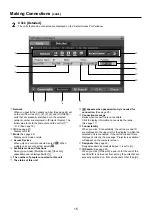
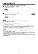
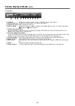
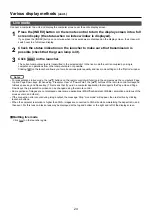
In [Network], select the network number set for the unit.

• Units powered on in the chosen network group are listed.
• This value is set to [1] by default.
• For details on setting a network number for the unit, see page 44.

4

Select the desired units, and click [OK].

The launcher appears and the connection with the unit is established. 
(“Description of the launcher” 

See page 22)

The launcher is not output on the display.

• Easy wireless connection cannot be made between the unit and the computer. (See page 56)
•  Automatic connection setting (See page 40)

1

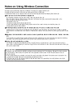
  • In the following situations, connections other than [U] are not possible.
    - Not logged in with Administrator rights
    - When using Windows Vista
 •  

Depending on the computer and wireless LAN card used, easy wireless set up may not be possible. If this is the case, 
the [Network] setting of “Select Access Port” window will be switched to [U] automatically. For details of the connection 
procedure, first close Wireless Manager ME 4.0, and then refer to pages 51-52.

2

 •  

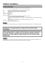
The initial network number for both the unit and Wireless Manager ME 4.0 is [1]. These numbers must match for the 
connection.

    To check the network number, check under WEB browser control. (See page 44).
 •  

When importance is placed on security, select the network number [2]-[4], because WEP* (wireless communication 
encryption) is set on these network numbers.

 •  

Important video/audio data is protected because AES* encryption processing takes place in advance for all network numbers, 
even if [ENCRYPTION] is set to [NONE]. 

  • Other network adapters may not be usable under easy wireless set up connections.
 •  

Connections to other networks connected through the wireless LAN card are broken under easy wireless set up connections.

 * “Glossary” (See page 55)

Making Connections 

(cont.)

Note

Notes

If the selected unit does not appear some time after this operation, select the network number again, and check the 
selection status.

Note

Содержание TY-FB10WPE

Страница 1: ...2 Operating Instructions Wireless Presentation Board Model No TY FB10WPE Before connecting operating or adjusting this product please read these instructions completely Please keep this manual for future reference English ...

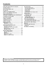
Страница 2: ... 24 Multi live mode 25 Multiple Source Live Mode 30 Multiple Source Multi Live Mode 32 Useful Functions 34 Selective area transmission 34 Secondary display transmission 35 One shot function 36 Shutter function 36 Pointer function 36 Functions used with each display method 37 Setting options 38 Setting option window 38 Using WebBrowser 41 Computer settings 41 Accessing from the Web browser 41 Descr...

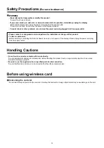
Страница 3: ...or change of this product To Service personnel Before removing or installing the Terminal Board be sure to turn power of the display off and unplug the power cord plug from the supply outlet Handling Cautions Do not touch connector contacts with hands directly To avoid electrostatic damage to internal parts before handling this product touch a large metallic object such as a steel cabinet to disch...

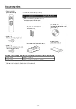
Страница 4: ...eless card protection cover Wireless card N5HZZ0000042 Remote control N2QAFB000009 Terminal function label 1 sheet Remote control batteries R6 UM3 x 2 Affix this label to applicable slot of the rear panel of the display Slot Nos of the display unit that are compatible with terminal board attachments 2 slot model SLOT1 SLOT2 3 slot model SLOT1 SLOT2 or SLOT2 SLOT3 Settings must be made for the disp...

Страница 5: ...Licensee caused by Licensee s reverse engineering decompiling or disassembly of the Software Article 6 After sales Service If a problem should occur with the Software while Licensee is using the Software Licensee should notify Panasonic of the problem by telephone or letter Panasonic shall undertake to notify Licensee of whether the problem is a known error in the program bug or whether the way in...

Страница 6: ...udio or video noise Wireless communication radio waves cannot penetrate steel reinforcements metal concrete etc Communication is possible through walls and floors made from materials such as wood and glass except glass containing wire mesh but not through walls and floors made from steel reinforcements metal concrete etc Using the unit outside the country It is forbidden to take the unit outside t...

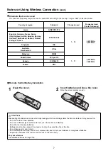
Страница 7: ...S 210 Taiwan DGT Open the cover 1 Insert batteries and close the cover Note the correct polarity and 2 Precautions Mishandling of batteries can cause electrolyte leakage which can damage items the fluid contacts and may cause a fire Do not mix old and new batteries Do not use different types at the same time ex zinc carbon and alkaline Do not burn or breakup batteries Batteries must not be exposed...

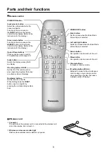
Страница 8: ...plays Numbered buttons Set the remote control ID While holding down the ID SET button input a 2 digit ID by pressing the corresponding number keys POWER OFF button Enter button Set the screen when Multi live Mode Index Style is selected Left and right buttons Select the screen when Multi live Mode Index Style is selected Return button No operation can be made to the unit Menu button No operation c...

Страница 9: ...ons to move the cursor and select the setting that corresponds to the slots being used When installing in SLOT1 SLOT2 Set to SLOT1 When installing in SLOT2 SLOT3 Set to SLOT2 1 Insert the wireless card into the unit Push it until a click is heard When removing the card push it until a click is heard and then remove it 2 Install the wireless card protection cover with the two screws Wireless card p...

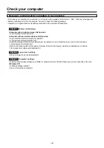
Страница 10: ...roperly recognized Is the wireless LAN card switched on Install the wireless LAN card driver beforehand For details on how to install the driver refer to the instructions accompanying the wireless card Refer to the following URL for the types of wireless LAN cards that system operation capabilities are confirmed http panasonic co jp pavc global projector Check 2 Logon user s settings Have you logg...

Страница 11: ...rly However some 802 11 b g wireless LAN may not allow connection to 802 11 g units Web browser Internet Explorer 6 0 or newer Netscape Communicator 7 0 or newer Operation is not guaranteed for all computers that meet the above conditions Note that operation is not guaranteed when used with system environments other than the above or on homemade computers This manual uses a computer with the Windo...

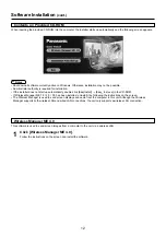
Страница 12: ...ager ME 1 0 2 0 3 0 has been installed uninstall it by following the instructions on the screen The Wireless Manager is used to send screen displays and audio from the computer to this unit Although the Wireless Manager supports both wireless LAN and wired LAN connections the unit only supports a wireless LAN connection This software is used to send screen images from a computer to the unit via a ...

Страница 13: ...ect the unit Some removable mediums start the programme automatically 5 When using without installing following functions are not available Selective area transmission See page 34 Secondary display transmission See page 35 Producing audio along with video at live mode Automatic connection by double clicking see page 40 Operation is slower compared to when the computer is used with Wireless Manager...

Страница 14: ...lick OK When the confirmation dialog box appears Click Yes When the Network Adapter Selection window appears ヂ Select the Wireless LAN ッ Select the adapter from the list and click OK If the confirmation dialog box appears click Yes Connections Although there are two possible connections methods using either Simple settings or Detailed settings only Detailed settings can be used with this unit Be s...

Страница 15: ...layed with デ The number of people connected to this unit ト The status of this unit ド appears when password entry is needed for connection See page 20 ナ Connection message Blinks when connection is not possible Click to display information on resolving the issue See page 17 ニ Connectability When you click Connectability the unit name and ID are displayed in the upper left of the display to which th...

Страница 16: ...w will be switched to U automatically For details of the connection procedure first close Wireless Manager ME 4 0 and then refer to pages 51 52 2 The initial network number for both the unit and Wireless Manager ME 4 0 is 1 These numbers must match for the connection To check the network number check under WEB browser control See page 44 When importance is placed on security select the network num...

Страница 17: ...network bridge is detected is installed When destination cannot be identified deactivate which is the cause Has your firewall in Windows XP been disabled Is Wireless Manager ME 4 0 registered in Exceptions Control Panel Security Center Windows firewall with the Windows XP SP 2 Are any firewall containing applications installed If you do not expect ever to use Network Bridge and see no need for it ...

Страница 18: ... card has been detected No response from the wireless LAN card Check the followings Wireless LAN Card conditions Driver version Latest Is the wireless LAN card effective Is your wireless LAN card properly recognized Some wireless cards may allow easy wireless set up connections to function if drivers are updated P 56 When the user does not have the administrator authority Please execute Easy Conne...

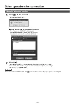
Страница 19: ...al network settings Click No to return to the launcher 2 Other operations for connection When the launcher is minimized right click on the notification area to display pop up menu and click End When connecting the unit for the first time The Preservation of a Profile window appears Set the save destination and file name and click OK If you do not need to create a profile click Close Canceling the ...

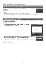
Страница 20: ... Port window connections can be added and deleted by the following operations Adding a connection When a unit with the mark is selected the window shown to the right appears Enter the password and click OK See page 48 Deleting a connection Select the connection to be deleted at the window shown in step 1 and click DELETE Click CANCEL at the password entry window to return to launcher See page 22 W...

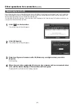
Страница 21: ... advance If you write down the ID displayed on the Select Access Port window in advance you can search a unit by the ID from next time Click on the launcher The window shown to the right appears 1 Enter four figures of desired unit s ID Enter only a 4 digit number and click Search Start Searching 3 When the unit of the applicable ID is found the computer will be connected to that unit and the stat...

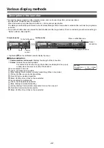
Страница 22: ...Connected units names IDs and their status are displayed in the pop up window when the cursor is on of the launcher When connected to one unit Green lit Transmission possible Blue blinking Own computer currently transmitting When in live mode Yellow lit Other user currently transmitting Red lit Communication impossible Black lit When the unit has not been selected When connected to multiple units ...

Страница 23: ...on the display screen See page 34 ド Secondary display transmission You can set the computer screen and the display screen to which the unit is connected to multi monitor mode and use the computer screen as the primary monitor and the display screen as the secondary monitor See page 35 ナ One Shot function The screen displayed when you click the mouse is display as a still image See page 36 ニ Shutte...

Страница 24: ...r to a unit and display the computer screen over the entire display screen Live mode For presentations in live mode the buttons on the remote control will function in the same way as the computer s Page Up and Page Down keys When using Presenter View of PowerPoint the buttons of the remote control correspond to Back space key and Space key This means that if you run a computer application that sup...

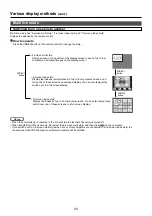
Страница 25: ...omputer screens You can also temporarily switch over one of these screens to a full screen display 4 screen multi style Assign an area of one quarter of the display screen to each of up to four computers and output images on the display screen When the unit starts up it resumes in the current style the last time the unit was turned off When transferring to the live mode first select the 4 screen m...

Страница 26: ...isplay screens temporarily change to full screen display To return to the original display click with the computer that click and select original positions with each computer Quitting 4 screen multi style Select and click the checked position in step 4 above In the 4 screen multi style the computer screens from all the computers connected to the unit can be transmitted to the unit If an image from...

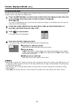
Страница 27: ...creen Check the status indication on the launcher to make sure that transmission is possible check that the green lamp is lit 2 Press the INDEX button of the remote control to switch the display screen to 4 screen index style See page 25 1 Click on the launcher The window shown to the right appears 3 Select and click the display position The computer image is transmitted to the area of correspondi...

Страница 28: ...l will function in the same way as the computer s Page Up and Page Down keys When using Presenter View of PowerPoint the buttons of the remote control correspond to Back space key and Space key This means that if you run a computer application that supports the Page Up and Page Down keys the presentation screen can be changed using the remote control Clicking on the launcher allows you to make var...

Страница 29: ...reen index style connect up to 16 computers to one unit and simultaneously display the screens for the 16 computers on index windows and also on a large screen While an enlarged image is displayed the buttons on the remote control will function in the same way as the computer s Page Up and Page Down keys When using Presenter View of PowerPoint the buttons of the remote control correspond to Back s...

Страница 30: ... button once or twice when index windows are displayed on the display screen the screen will switch over to a full screen display 1 Select the network number of the desired units from Network Units powered on in the chosen network group are listed 4 Click of Access Device 3 Select the desired units and click OK Selected units are displayed in pink If click again selected items are canceled If clic...

Страница 31: ...set to full screen display the images are displayed onto the other selected units The greater the number of units the slower the transmission Clicking on the launcher allows you to make various picture quality and live mode settings on the Option window Sound cannot be output in the multiple source live mode If the connection error occurs during image output the message Stop Live mode will appear ...

Страница 32: ... twice when index windows are displayed on the display screen the screen will switch over to a full screen display 1 Select the desired units and click OK Selected units are displayed in pink If click again selected items are canceled If click OK the connection with the units is established 5 Select the network number of the desired units from Network Units powered on in the chosen network group a...

Страница 33: ...p 8 above Units only in the same network are selectable If a display whose screen is not set to full screen display is included among the selected displays will be grayed out preventing the display from being selected The greater the number of units the slower the transmission In multiple source multi live mode even when the remote control INDEX button is pressed no operation will result Clicking ...

Страница 34: ...ay with the selective area window You can perform operations in the selective area window with the same operation for moving or changing the window on the computer screen If clicking the selective area window automatically fit the inside window s size If clicking the selective area window changes to its default size If clicking the selective area transmission function ends 2 Selective area transmi...

Страница 35: ...n will be displayed as the third monitor in Display Properties of Windows Quitting secondary display transmission Click on the launcher again If you are using secondary display transmission function and displaying a secondary monitor screen in multiple source multi live mode once is pressed on one of the computers the full screen display from that computer will override all the rest and the second...

Страница 36: ...ay only the required parts of the computer screen as still images you can use the one shot function to send the parts which you have selected using the selective area transmission function Momentarily blanks the screen and mutes audio Click on the launcher The image is turned off When sound is output the sound also goes out 1 Click again The image comes back 2 Shutter function The shutter function...

Страница 37: ...t Live mode Multi live mode One shot When connected to multiple units Multiple Source Live Mode Multiple Source Multi Live Mode One shot Yes No Available when no live is done You can operate them by the launcher when no live is done and display screen is set to be full screen display the status when no index is displayed Sound can be output only in live mode See page 38 ...

Страница 38: ... transmitted screen In the 4 screen and 16 screen index style modes they are also displayed at the bottom of each image Alphanumerics are not displayed when the check mark has been removed Produce audio along with video at live mode You can set this when you want to output audio data from a unit in live mode Also volume setting operated from the launcher is different from the Windows volume settin...

Страница 39: ... one alphabet to be used with the key chosen in step 2 3 Click Setting The shortcut key set in step 2 3 appears in the blank space If click Clear the shortcut settings are canceled 4 Note In live mode and multi live mode the shortcut key switches the mode without stopping live mode Use Pause key to stop continue Live Mode Stops live mode and multi live mode Use PrintScreen key to execute One Shot ...

Страница 40: ...matic connection setting You can perform automatic settings for newly connected units Other The version information of Wireless Manager ME 4 0 is displayed when on the Option window is clicked Version information When Profile Creation is clicked the Preservation of a Profile window appears Create profiles with information about connected units You can use the created profile to connect automatical...

Страница 41: ...tions Internet Option 1 Enabling JavaScript Enable JavaScript if it has been disabled Select Security and set the security level to Default Level or select Custom Level and check the Enable checkbox under Active scripting 2 Accessing from the Web browser Click on the launcher Or start the WEB browser and enter the IP address of the unit if you know it 1 Select the language English Japanese 2 Enter...

Страница 42: ...trl R keys for example to update the screen Connection cannot be made while the WebBrowser is set to dial up network Cancel the dial up network setting It may take some moments for WebBrowser to start up Using WebBrowser cont Description of Each Screen The following initial screen monitor information is displayed once authentication at time of startup has ended Notes Menu items are displayed The H...

Страница 43: ...ious display settings To access this page from another page click Display Control on the menu and Basic and Advanced on the submenu Display control window Connection with the display may not be possible immediately after the power is turned on In this case wait a bit and then make the connection again It is necessary to set up the display when using this function See page 9 Basic control window Ad...

Страница 44: ...value set on the application is other than the network number set for the unit In addition since the security levels differ for each select the optimum network for the environment being used 1 Initial settings simple connection mode 2 to 4 The WEP setting Key information is a fixed value USER1 to USER3 Allows detailed network and security settings Also used for settings during infrastructure mode ...

Страница 45: ... enter the same character string as that of SSID set on the computer to be connected MODE INFRASTRUCTURE Connect through access point 802 11 AD HOC Connect computer directly without access point Glossary See page 54 55 Detailed Network Settings Screen 1 3 4 Detailed Network Settings Screen 2 3 5 MODE INFRASTRUCTURE MODE 802 11 AD HOC AUTHENTICATION Sets the authentication system OPEN When connecti...

Страница 46: ...e set If a 64 bit key is selected enter 5 one byte alphanumeric characters 10 digits when using hexadecimal If a 128 bit key is selected enter 13 one byte alphanumeric characters 26 digits when using hexadecimal AES When using AES for the encryption system This can be selected when AUTHENTICATION is WPA PSK KEY Sets the key KEY can be set using 8 to 63 alphanumeric characters or 64 hexadecimal dig...

Страница 47: ...screen Important data is protected even if ENCRYPTION is set to NONE for video and audio data because AES encryption is carried out for all network numbers beforehand Default settings of USER1 USER3 NETWORK USER1 USER3 IP DHCP OFF HOST NAME FB10WP SSID Panasonic Display MODE AD HOC AUTHENTICATION OPEN ENCRYPTION NONE IP ADDRESS 192 168 10 100 SUBNETMASK 255 255 255 0 GATEWAY 192 168 10 1 Note ...

Страница 48: ...Sets the password to use when accessing the WEB browser control screen Click WEB on the submenu Enter the old password and the new password and then click OK No password is set when shipped from the factory The password may contain one byte alphabetic characters upper and lower case numeric characters and symbols Enter up to 16 characters ...

Страница 49: ...Wireless Manager ME4 0 Click WM on the submenu Password Enable Set when enabling authentication Next enter the password The password may contain one byte alphabetic characters upper and lower case and numeric characters Enter up to 8 characters Disable Set when you are not using authentication ...

Страница 50: ...ntrol Access is not allowed unless the remote control ID matches that set for the unit This ID can be set using the remote control as follows Click Remote control ID Settings on the menu Remote control ID Settings Screen After entering an ID click OK One byte numeric characters can be used Enter up to 2 digits ...

Страница 51: ...he appropriate settings under Computer Settings must first be made beforehand by someone with PC administrator rights Next logon as a restricted user or GUEST and start Wireless Manager ME 4 0 Confirm to your system administrator before changing any settings The example below is for when the unit is being used under default settings Connect the unit to the computer as the computer administrator 1 ...

Страница 52: ...t d Click Add of Preferred networks on Wireless Networks tab in Wireless Network Connection Properties window Wireless network properties window appears When the Wireless Networks tab does not appear refer to page 57 e Make the SSID network authentication data encryption and communication mode settings the same as those of step 2 and click OK f Click OK in Wireless Network Connection Properties wi...

Страница 53: ...ontrol once 1 Then Push key three times RESET is displayed at the upper left of the screen 2 You can return the changed settings to the initial conditions Exit the Wireless Manager before proceeding RESET ON OFF INPUT ASPECT VOL ENTER RETURN MENU ID ALL INDEX ID SET ...

Страница 54: ...o the data distribution destination is called the IP address The same IP address cannot be used within the same LAN 20 45 51 DHCP Abbreviation for Dynamic Host Configuration Protocol This function automatically assigns IP addresses to the connected equipment If a device with the DHCP server function is present within a LAN it automatically assigns IP addresses to the connected equipment 45 51 Subn...

Страница 55: ...which the same key is used for both encryption and decryption are shared key encryptosystem and common key encryptosystem 45 51 WPA PSK This is a standard covering encryption methods used in wireless LAN It provides greater security than WEP and has functions such as a user authentication function and also TKIP encryption protocol which automatically changes the encryption key at fixed intervals A...

Страница 56: ...tting has been detected Is Network Bridge enabled Some computers with Windows XP may have Network Bridge a built in function of Windows XP enabled this will prevent a wireless connection The settings in Network Bridge must be changed in order to make a wireless connection If you do not expect ever to use Network Bridge and see no need for it delete it from your system To verify whether your system...

Страница 57: ...on the internet 7 Select the scope and click OK 8 Click OK in the Add a Program window 9 Click OK in the Windows Firewall window With this the Wireless Manager ME 4 0 firewall will be deleted When another firewall has been detected Are any firewall containing applications installed If any applications which contain firewalls are installed the installation may hang up at the Projector search in pro...

Страница 58: ...uch factors as the location radio signal conditions or distance Avoid placing metal objects or other conductors near the wireless LAN antenna of a computer otherwise the transfer rate may be slower When WEP is set the image data is converted so transfer takes time Image display is slow or animation is not displayed smoothly Is the computer CPU speed slow See page 11 Live mode depends largely upon ...

Страница 59: ...ge and characters are difficult to read Click Start Control panel Appearance and Themes Display Then open the Settings tab of the Display Properties window and set Color quality to Medium 16 bit or higher Screen saver is not displayed properly in live mode Some screen savers may not be displayed properly in the live mode Disable screen saver function using Live Mode Settings in Option window of Wi...

Страница 60: ...60 Declaration of Conformity ...

Страница 61: ...schreven A is conform de vereisten van onderstaande EU wetgeving B en geharmoniseerde normen C Het product voldoet daarnaast ook aan de Richtlijnen van de Raad D Norwegian Gjenstand for erklæringen som beskrives ovenfor A er i overensstemmelse med kravene ifølge EU lovene B og de harmoniserte normer C Produktet tilfredsstiller også EU rådets direktiver D Finnish Yllä mainitussa vaatimustenmukaisuu...

Страница 62: ... normami C Výrobok taktiež spĺňa direktívy Rady D Estonian Ülalkirjeldatud deklareeritav toode A vastab Euroopa Ühenduse määruste B ja ühtsete standardite C nõuetele Samuti vastab toode Euroopa Nõukogu direktiivide D nõuetele Latvian Augstākminētās deklarācijas objekts A atbilst šādu ES likumdošanas aktu prasībām B un vienotajiem standartiem C Produkts atbilst arī Padomes direktīvu prasībām D Lith...

Страница 63: ...MEMO 63 ...
Страница 64: ...may be applicable for incorrect disposal of this waste in accordance with national legislation For business users in the European Union If you wish to discard electrical and electronic equipment please contact your dealer or supplier for further information Information on Disposal in other Countries outside the European Union These symbols are only valid in the European Union If you wish to discar...

Отзывы: