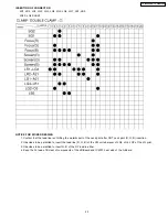
INSERTION OF CONNECTOR
LR1, LR2, LG1, LG2, LG3, LG4, LG5, LG6, LG7, LB1, LB2,
LR20, LG20, LB20
NOTICE FOR WORE DRESSING
1. Confirm that the lead line isn’t hitting the metallic part of the neck print after CRT neck print (R, G, B) insertion.
2. It decides to be permitted to insert the lead line (R, G, B) of the VM coil wherever of LG5, LG6, LG7 of the LG print.
3. It decides to be permitted to insert G, B of the DY lead in either.
4. Keep the Fo lead of B clear of components of the LB-Board and IC2301 heat sink of the A-Board.
45
TX-47P800HQ / TX-47P800HZ
Содержание TX-47P800HQ TX-47P800HZ
Страница 15: ...15 TX 47P800HQ TX 47P800HZ ...
Страница 16: ...6 3 Option Descrition 16 TX 47P800HQ TX 47P800HZ ...
Страница 17: ...17 TX 47P800HQ TX 47P800HZ ...
Страница 18: ...18 TX 47P800HQ TX 47P800HZ ...
Страница 41: ...Fine Convergence Control Chart 41 TX 47P800HQ TX 47P800HZ ...
Страница 42: ...42 TX 47P800HQ TX 47P800HZ ...
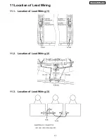
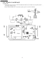
Страница 44: ...11 4 Location of Lead Wiring 4 44 TX 47P800HQ TX 47P800HZ ...
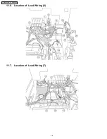
Страница 48: ...11 6 Location of Lead Wiring 6 11 7 Location of Lead Wiring 7 48 TX 47P800HQ TX 47P800HZ ...
Страница 49: ...11 8 Location of Lead Wiring 8 11 9 Location of Lead Wiring 9 49 TX 47P800HQ TX 47P800HZ ...
Страница 50: ...50 TX 47P800HQ TX 47P800HZ ...


