11
Get
ting St
arted
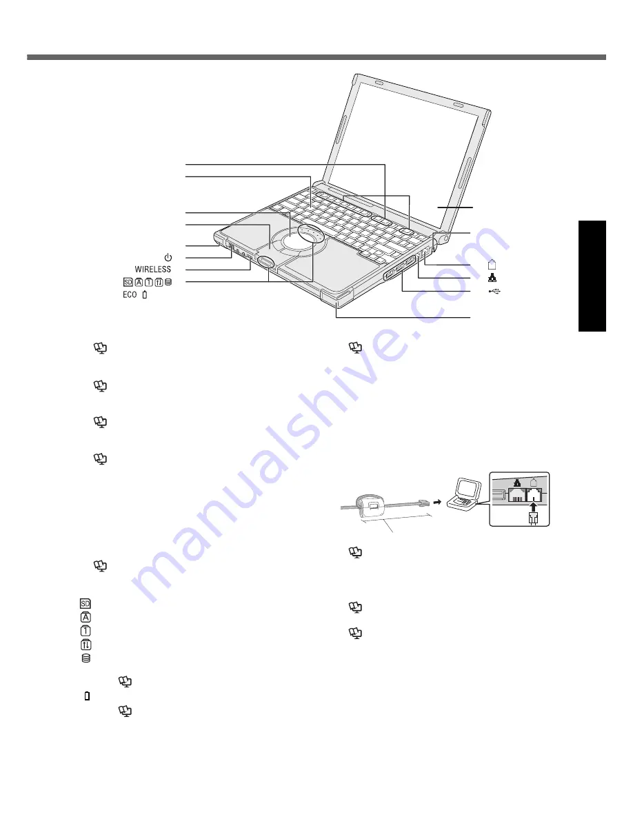
Description of Parts
A :Function Key
Reference Manual
“Key Combinations”
B :Keyboard
C :Touch Pad
Reference Manual
“Using the Touch Pad”
D :Bluetooth Antenna
<Only for model with Bluetooth>
Supplementary Instructions
of Bluetooth
E : Wireless LAN Antenna
<Only for model with wireless LAN>
Reference Manual
“Wireless LAN”
F : Power Switch
page 14
Power Indicator
• Off: Power off/Hibernation
• Green: Power on
• Blinking green: standby
G :Wireless Switch
Switch the wireless devices to on (right side) or to off (left side).
<Only for model with wireless LAN/wireless WAN/Bluetooth>
Reference Manual
“Disabling/Enabling Wire-
less Communication”
H :LED Indicator
: SD/SDHC Memory Card status
: Caps lock
: Numeric key (NumLk)
: Scroll lock (ScrLk)
: Hard disk drive status
ECO : Economy Mode (ECO) status
Reference Manual
“Battery Power”
: Battery status
Reference Manual
“Battery Power”
I : LCD/Touchscreen
Reference Manual
“Using the Touchscreen”
J : Security Lock
You can connect a Kensington cable. Refer to the instruc-
tion manual of the cable. The security lock and cable is a
theft prevention device. Matsushita Electric Industrial Co.,
Ltd. will bear no responsibility in the event of theft.
K :Modem Port
• Be sure to use the included modem telephone cable,
and insert the ferrite core side of modem telephone
cable into the modem port on the computer
.
• Do not move/remove the ferrite core of modem tele-
phone cable.
Reference Manual
“Modem”
L : LAN Port
If the Mini Port Replicator is connected to the computer,
connect the LAN cable to the LAN port on the Mini Port
Replicator. You cannot use the LAN port on the computer.
Reference Manual
“LAN”
M :USB Ports
Reference Manual
“USB Devices”
I
J
K
L
M
E
A
B
C
D
E
F
G
H
90
mm
{3.5 "} or less


