


27
TH-65PF11EK
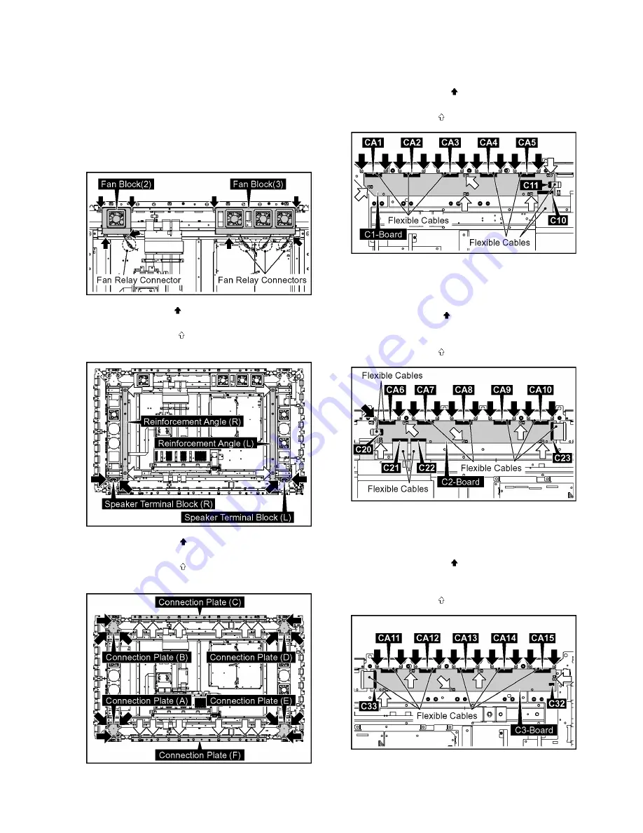
8.19. Removal of C1, C2, C3, C4, C5,
C6-Board
1. Remove the S1-Board Block.
(Refer to Removal of S1-Board).
2. Remove the Cabinet Block.
(Refer to Removal of Front Glass, V1, V2-Board and Cab-
inet Assy)
3. Disconnect the Fan Relay Connectors.
4. Remove 8 screws and then remove the Fan Blocks (2, 3).
5. Remove 4 screws ( ) and then remove the Speaker Ter-
minal Blocks (L), (R).
6. Remove 4 screws ( ) and then remove the Reinforce-
ment Angles (L), (R).
7. Remove 12 screws ( ) and then remove the Connection
Plates (A, B, D, E).
8. Remove 12 screws ( ) and then remove the Connection
Plates (C, F).
8.19.1.
Removal of C1-Board
1. Remove the flexible cables from the connectors (C10,
C11).
2. Remove 10 screws ( ) and then remove the flexible
cables from the connectors (CA1, CA2, CA3, CA4, CA5).
3. Remove 5 screws ( ) and then remove C1-Board.
8.19.2.
Removal of C2-Board
1. Remove the flexible cables from the connectors (C20,
C21, C22, C23).
2. Remove 10 screws ( ) and then remove the flexible
cables from the connectors (CA6, CA7, CA8, CA9,
CA10).
3. Remove 5 screws ( ) and then remove C2-Board.
8.19.3.
Removal of C3-Board
1. Disconnect the connector (C32).
2. Remove the flexible cable from the connector (C33).
3. Remove 10 screws ( ) and then remove the flexible
cables from the connectors (CA11, CA12, CA13, CA14,
CA15).
4. Remove 5 screws ( ) and then remove C3-Board.
Содержание TH-65PF11EK
Страница 7: ...7 TH 65PF11EK 3 2 Applicable signals ...
Страница 9: ...9 TH 65PF11EK 5 Operating Instructions ...
Страница 14: ...14 TH 65PF11EK 6 2 IIC mode structure following items value is sample data ...
Страница 35: ...35 TH 65PF11EK 9 1 4 Adjustment Volume Location 9 1 5 Test Point Location ...
Страница 37: ...37 TH 65PF11EK ...
Страница 39: ...39 TH 65PF11EK ...
Страница 40: ...40 TH 65PF11EK ...
Страница 50: ...TH 65PF11EK 50 ...
Страница 51: ...51 TH 65PF11EK 11 Wiring Connection Diagram 11 1 Wiring 1 ...
Страница 52: ...52 TH 65PF11EK 11 2 Wiring 2 ...
Страница 53: ...53 TH 65PF11EK 11 3 Wiring 3 ...
Страница 54: ...54 TH 65PF11EK ...
Страница 55: ...TH 65PF11EK 55 12 Schematic Diagram 12 1 Schematic Diagram Notes ...
Страница 185: ...Model No TH 65PF11EK Note ...
Страница 186: ...Model No TH 65PF11EK Exploded View ...
Страница 187: ...Model No TH 65PF11EK Cabinet part location ...
Страница 188: ...Model No TH 65PF11EK Fan part location ...
Страница 189: ...Model No TH 65PF11EK Flat cable ...
Страница 190: ...Model No TH 65PF11EK Accessories ...
Страница 191: ...Model No TH 65PF11EK Packing 1 ...
Страница 192: ...Model No TH 65PF11EK Packing 2 ...


