


79
12 Service Position
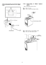
12.1. Main Unit (SU-HTB550)
Note: For description of the disassembly procedures, see the Section 11
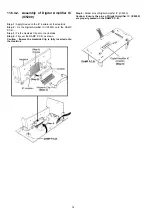
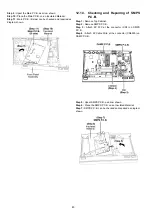
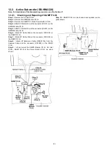
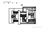
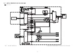
12.1.1. Checking and Repairing of Main
P.C.B. (Side A)
Step 1 :
Remove Top Cabinet.
Step 2 :
Main P.C.B. (A side) can be checked and repaired as
diagram shown.
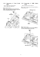
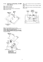
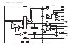
12.1.2. Checking and Repairing of Main
P.C.B. (Side B)
Step 1 :
Remove Top Cabinet.
Step 2 :
Remove Main P.C.B..
Step 3 :
Remove Front Panel Block.
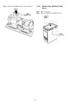
Step 4 :
Attach 2P Cable Wire at the connector (CN2206) on
Main P.C.B..
Step 5 :
Attach 40P FFC at the connector (CN2201) on Main
P.C.B..
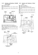
Step 6 :
Attach 17P FFC at the connector (CN2205) on Main
P.C.B..
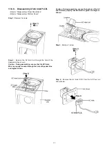
Step 7 :
Attach 11P FFC at the connector (CN2204) on Main
P.C.B..
Step 8 :
Attach 9P FFC at the connector (CN2202) on Main
P.C.B..
Содержание SU-HTB550GK
Страница 5: ...5 1 6 Caution for the AC Mains Lead For GS only ...
Страница 7: ...7 1 8 Safety Installation Instructions ...
Страница 12: ...12 5 General Introduction 5 1 About VIERA Link ...
Страница 26: ...26 ...
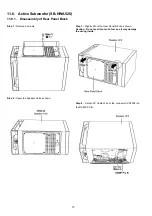
Страница 30: ...30 11 1 3 Active Subwoofer SB HWA520 ...
Страница 33: ...33 11 3 2 2 Standing Position 11 3 3 Active Subwoofer SB HWA520 ...
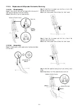
Страница 53: ...53 Step 5 Remove the Speaker Base Step 6 Remove 2 screws Step 7 Push up and remove the Front Ornament Assembly ...
Страница 84: ...84 ...
Страница 96: ...96 ...
Страница 98: ...98 ...
Страница 120: ...120 ...
Страница 135: ...135 99 W_SDO O Wireless control Serial Data Out 100 W_SCL O Wireless control Serial Clock Pin No Mark I O Function ...
Страница 136: ...136 ...
Страница 142: ...142 ...