background image

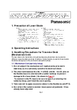
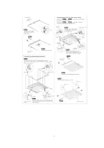
3.2. Grounding for electrostatic breakdown prevention

1. Human body grounding

 Use the anti-static wrist strap to discharge the static electricity 
from your body. (As shown in 

Fig. 2

.)

2. Work table grounding

 Put a conductive material (sheet) or steel sheet on the area where 
the optical pickup is placed, and ground the sheet.

Caution:

The static electricity of your clothes will not be grounded through 
the wrist strap. So, take care not to let your clothes touch the 
traverse deck (optical pickup).

Fig. 2

4. Operation Checks and Main Component 
Replacement Procedures

4

Содержание SJ-MJ70

Страница 1: ...ORDER No AD9903073C2 Portable MD Player SJ MJ70 Colour S Silver Type Areas EB Great Britain EG Germany and Italy etc SPECIFICATIONS Specifications 1 ...

Страница 2: ...mensions 71 7x79 7x14 5 mm incl projecting parts 73 3x81 3x15 3 mm Weight 94 g with battery 69 g without battery Play time When used in hold mode at 25 C on a flat stable surface Battery type Play time Rechargeable About 7 hours Panasonic alkaline About 24 hours Both together About 32 hours Charger Input AC 120 240 V for Continental Europe AC230 240 V for UK 50 Hz 4W Output DC 340 mA for Continent...

Страница 3: ...optical pickup 1 Do not subject the mechanism unit optical pickup to static electricity as it is extremely sensitive to electrical shock 2 The short land between the No 11 GND and No 12 LD pins on the flexible board is shorted with a solder build up to prevent damage to the laser diode As shown in Fig 1 To connect to the PC board be sure to open by removing the solder build up and finish the work ...

Страница 4: ...2 2 Work table grounding Put a conductive material sheet or steel sheet on the area where the optical pickup is placed and ground the sheet Caution The static electricity of your clothes will not be grounded through the wrist strap So take care not to let your clothes touch the traverse deck optical pickup Fig 2 4 Operation Checks and Main Component Replacement Procedures 4 ...

Страница 5: ...5 ...

Страница 6: ...6 ...

Страница 7: ...7 ...

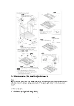
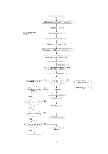
Страница 8: ... Note If you exchange mechanism unit RAE1610Z when you repair you must perform the automatic adjustment and checking of playback only disc magneto optical disk at the adjsutment mode Discs to prepare 1 Test disc Playback only disc 8 ...

Страница 9: ...onent Replacement Procedures B Set the battery C While pressing the battery cover to connect the battery power continuously press the OPEN CLOSE switch As shown in Fig 3 D The optical pickup moves up and down and emits a laser Caution Do not look directly at the laser light source If the laser does not emit a beam follow the item of operation check in Troubleshooting Guide and check for a malfunct...

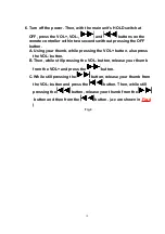
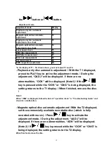
Страница 10: ...ur thumb while pressing the VOL button also press the VOL button B Then while still pressing the VOL button release your thumb from the VOL and press the button C While still pressing the button release your thumb from the VOL button and press the button Then while still pressing the button release your thumb from the button and then from the button a c are shown in Fig 4 Fig 4 10 ...

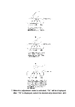
Страница 11: ...7 When the adjustment mode is activated TA will be displayed After TA is displayed select the desired adjustment item with 11 ...

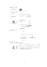
Страница 12: ...t mode During the adjustment OADJ will be displayed If there are no abnormalities OOK will be displayed Note1 If the key is pressed while the OOK or ONG is being displayed the setting returns to the T1 display When finished remove the disc Note 1 When ONG is displayed follow the item of operation check in Troubleshooting Guide and check for a malfunction Magneto optical disc automatic adjustment W...

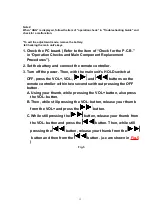
Страница 13: ...er 3 Turn off the power Then with the main unit s HOLD switch at OFF press the VOL VOL and buttons on the remote controller within two seconds without pressing the OFF button A Using your thumb while pressing the VOL button also press the VOL button B Then while still pressing the VOL button release your thumb from the VOL and press the button C While still pressing the button release your thumb f...

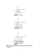
Страница 14: ...4 When entering the main unit s key check mode KEY will be displayed 14 ...

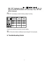
Страница 15: ...ck the following voltage for each key Key Test point ON OFF IC201 35 pin 0V 2 4V HOLD TPX110 2 4V 0V VOL TP307 0V 2 4V VOL TP307 0 6V 2 4V TP307 1 2V 2 4V TP307 1 8V 2 4V To exit the main unit s key check mode remove the battery Note Refer to Printed Circuit Board and Wiring Connection Diagram for the test points 6 Troubleshooting Guide 15 ...

Страница 16: ...16 ...

Страница 17: ...17 ...

Страница 18: ...18 ...

Страница 19: ...19 ...

Страница 20: ...20 ...

Страница 21: ...7 Schematic Diagram Notes 7 1 Schemtic Diagram Notes This schematic diagram may be modified at any time with the development of new technology Notes S201 Volume VOLUME switch 21 ...

Страница 22: ...k have special characteristics important for safety Furthermore special parts which have purpose of fire retardant resistors high quality sound capacitors low noise resistors etc are used When replacing any of components be sure to use only manufacture s specified parts shown in the parts list Caution IC and LSI are sensitive to static electricity Secondary trouble can be prevented by taking care ...

Страница 23: ...d input terminal 6 E 7 D I Main beam signal that I V converted input termianl 8 C 9 B 10 A 11 VEE GND terminal 12 NC Not used open 13 LDO O APC output terminal 14 NC Not used open 15 LDS I Laser light quantity that I V converted input terminal 16 LDREF I Laser control signal input terminal 17 TBAL I Tracking balance control signal input terminal 18 TOFFSET I Tracking offset control signal input te...

Страница 24: ...rminal 28 TE O Tracking error signal output terminal 29 ABCD O Main beam light quantity signal output terminal 30 HFLI I For making HFL signal input terminal when group mode 31 NC Not used open 32 BOTTOM O Bottom signal of RF signal output terminal 33 PEAK O Peak signal of RF signal output terminal 34 HFL O Track detection signal input terminal 35 RFVEE GND terminal 36 EQ0 O RF equalizer output te...

Страница 25: ...45 SETR I Band pass filter set ting input terminal 46 CAD I Capaciter for DC cut of Wobble signal connect terminal 47 BWCT I Band pass filter select terminal for wobble signal 48 SLEEP I Sleep mode terminal H power supply ON L power supply OFF Connected to power supply through capacitor 11 2 IC101 LC89641 MSP 25 ...

Страница 26: ...al output terminal 5 TBAL O Tracking balance control signal output terminal 6 LDREF O Laser control signal output terminal 7 FG I Speed pulse input terminal 8 SPPWMF O Spindle PWM output terminal 9 SPPWMR 10 SLPWMF O Sled PWM output terminal 11 SLPWMR 12 FOPWMF O Focus PWM output terminal 13 FOPWMR 14 TRPWMF O Tracking PWM output terminal 15 TRPWMF 16 VSS GND terminal 17 XIN I Crystal oscillator i...

Страница 27: ...D2 I Power supply terminal 28 OUTL O 1bit DAC L channel output terminal 29 OUTR O 1bit DAC R channel output terminal 30 AVSS GND terminal 31 VDD3 I Power supply terminal 32 35 MAD3 MAD0 O Address output terminal to DRAM 36 38 MAD9 MAD11 39 MRAS O RAS signal output terminal to DRAM 40 VSS GND terminal 41 VDD1 I Power supply terminal 42 MWE O WE signal output terminal to DRAM 43 MD1 I O Data in outp...

Страница 28: ...utput terminal Not used open 63 VDD1 I Powe supply terminal 64 VSS GND terminal 65 VDD2 I Power supply terminal 66 CL I CPU interface data clock input terminal 67 CE I CPU interface chip enable signal input terminal 68 DI I CPU interface data input terminal 69 DO O CPU interface data output terminal 70 WRQ O CPU interface interrupt signal output terminal 71 INT 72 ADIPW0 I Wobble signal input term...

Страница 29: ... I RF equalizer input terminal 84 TEST2 I Input terminal for test Connected to power supply 85 VDD2 I Power supply terminal 86 RESET I System reset signal input terminal 87 HFL I Track detection signal input terminal 88 TEST1 I Input terminal for test Connected to power supply 89 VDD1 I Power supply terminal 90 VSS GND terminal 91 AVDD1 I Power supply terminal 92 PEAK I Peak signal of RF signal in...

Страница 30: ...unction 99 DSW1 O Disc mode setting output terminal H track is pit row L track is group 100 DSW0 O Disc mode setting output terminal H low reflection rate disc L high reflection rate disc 11 3 IC201 MN101C28CAB SYSTEM CONTROL 30 ...

Страница 31: ... KEY I Remocon key input terminal 7 DOCTOR I Check mode input terminal L check mode Connected to power supply through resistor 8 AN6 Not used connected to GND 9 SE I Sled error voltage input terminal 10 VREF I Reference voltage input terminal 11 VDD I Power supply terminal 12 OSC2 I System clock input terminal 8MHz 13 OSC1 O System clock output terminal 8MHz 14 VSS GND terminal 15 XI I Sub clock i...

Страница 32: ...put terminal 27 Not used open 28 SE TR O Band pass filter set terminal 29 Not used open 30 BWCT O Band pass filter select output terminal 31 INTB I CPU interface interrupt input terminal 32 WRQB 33 REM WUP I Remocon wake up interrupt input terminal 34 OPEN SW I Cover open close detect terminal H open 35 PLAY KEY I Play key input terminal L STOP PLAY 36 AGC TC O RF AGC select output terminal Not us...

Страница 33: ...data input terminal 56 Not used open 57 HOLD I Hold switch input terminal L Hold switch off 58 MUTEA O Analog mute A output terminal 59 MUTEB O Analog mute B output terminal 60 Not used open 61 STBY2 O 4ch driver IC stand by 2 output terminal 62 RFCONT O RF amp power control output terminal 63 SEDIR I Sled error direction input terminal 64 TBALOK O Tracking balance adjustment output terminal H adj...

Страница 34: ...dle motor coil W output terminal 13 SP VM2 I Power supply terminal for part of spindle power 14 NC Not used open 15 SP V OUT O Spindle motor coil V output terminal 16 NC Not used open 17 SP PG1 GND terminal 18 NC Not used open 19 SP U OUT O Spindle motor coil U output terminal 20 SP VM1 I Power supply terminal for part of spindle power 21 SP COM I Spindle motor coil center input terminal 22 SP W I...

Страница 35: ...erminal 41 VCC1 I Power supply terminal 42 VCC2 43 IN 1F I H bridge 1 forward input terminal 44 IN 1R I H bridge 1 reverse input terminal 45 IN 2F 46 IN 2R I H bridge 2 reverse input terminal 47 EXT CLK I Not used open 48 CIP Charge pump capaciter 1 connect terminal 49 CIM Charge pump capaciter 1 connect terminal 50 C2P Charge pump capaciter 2 connect terminal 51 C2M Charge pump capaciter 2 connec...

Страница 36: ...erminal 72 NC Not used open 73 PW1VM I Power supply terminal 74 NC Not used open 75 PW1 OUT O Half bridge 1 output terminal 76 NC Not used open 77 PW PG GND terminal 78 NC Not used open 79 PW2 OUT O Half bridge 2 output terminal 80 PW2 VM I Power supply terminal 12 Supply of Rechargeable Battery Ass y as Replacement Parts Please take note of the following points relating to Battery Carrying Case t...

Страница 37: ...tery Carrying Case and use it Be sure to carry Rechargeable Battery Carrying Case If not it may either heat or ignite by shorting with a metal as shown in Fig 7 Fig 7 14 Replacement Parts List 14 1 Replacement Parts List Notes Important safety notice Components identified by mark have special characteristics important for safety Funrthermore special parts which have purposes of fire retardant resi...

Страница 38: ...M 1M 1 000K OHM The marking RTL indicates that the Retention Time is limited for this item After the discontinuation of this assembly in production the item will continue to be available for a specific period of time The retention period of availability is dependant on the type of assembly and in accordance with the laws governing part and product retention After the end of this period the assembl...

Страница 39: ...OLD KNOB 1 9 RHQ0075 S SCREW 6 10 RKK0122 S BATTERY COVER 1 11 RAE1610Z MECHANISM UNIT 1 11 1 RDG0446 INTERMEDIATE GEAR 1 11 2 RHW11011 WASHER 1 11 3 RMC0370 SPRING 1 11 4 BQL1A1CWD TRAVERSE MOTOR 1 11 5 RHD14067 SCREW 1 11 6 RJC99034 R BATTERY TERMINAL 1 11 7 RMX0147 STOPPER RUBBER 1 11 8 RHD14074 SCREW 1 11 9 RHD14066 SCREW 1 14 RJC99035 R BATTERY TERMINAL 1 15 RJR0195 BATTERY SHAFT 1 16 RHD1406...

Страница 40: ...UENJ104KBQ 6 3V 0 1U 1 C25 RCST0GZ156RG 4V 15U 1 C27 29 ECUE1H102KBQ 50V 1000P 3 C101 RCST0EZ226RE 2 5V 22U 1 C102 ECUENJ104KBQ 6 3V 0 1U 1 C104 RCST0EZ226RE 2 5V 22U 1 C107 14 ECUENJ104KBQ 6 3V 0 1U 8 C115 ECUE1C103KBQ 16V 0 01U 1 C116 23 ECUENJ104KBQ 6 3V 0 1U 8 C124 ECUENA473KBQ 10V 0 047U 1 C125 ECUE1C103KBQ 16V 0 01U 1 C126 ECUENJ104KBQ 6 3V 0 1U 1 C127 ECUE1C223KBQ 16V 0 022U 1 C128 ECUENJ10...

Страница 41: ...C309 11 ECUENC333KBQ 16V 0 033U 3 41 ...

Страница 42: ...P301 02 RJS2A7104T CONNECTOR 4P 2 D402 RB081L20TE25 SCHOTTKY DIODE 1 D403 MA729TX DIODE 1 IC1 LA9606W TFM RF IC 1 IC101 LC89641 MD DSP IC 1 IC102 MNA7400CWA1T 16MDRAM PBFREE 1 IC201 MN101CP28DAB MICON OR MN101CP28DAB 1 IC202 AK93C45AV L E2PROM 1 IC203 XC61AC1902MR RESET IC 1 IC301 BD6601KVT 1CHIP DRIVER IC 1 IC402 XC6368A241MR D D CONVERTER IC 1 IC501 NJU7082BVTE1 IC 1 JK501 RJJ36TK06 C HEADPHONE ...

Страница 43: ...03 ERJ2GEJ184X 1 4W 180K 1 R104 ERJ2GEJ334X 1 4W 330K 1 R105 ERJ2GEJ683X 1 4W 68K 1 R106 ERJ2GED113X 1 4W 11K 1 R107 ERJ2GEJ103X 1 4W 10K 1 R108 ERJ2GEJ224X 1 4W 220K 1 R112 ERJ2GEJ473X 1 4W 47K 1 R114 ERJ2GEJ474X 1 4W 470K 1 R122 ERJ2GEJ121X 1 4W 120 1 R125 ERJ2GEJ332X 1 4W 3 3K 1 R126 ERJ2GEJ103X 1 4W 10K 1 R127 ERJ2GEJ333X 1 4W 33K 1 R128 ERJ2GEJ472X 1 4W 4 7K 1 R130 ERJ2GED273X 1 4W 27K 1 R131...

Страница 44: ...6W 4 7K 2 R509 ERJ2GEJ472X 1 4W 4 7K 1 R513 14 ERJ2GEJ153X 1 4W 15K 2 R517 EXB28V103JX 1 32W 10K 1 RX901 ERJ2GEJ103X 1 4W 10K 1 S201 02 EVQPUM02K SW VOLUME 2 S203 04 EVQPUL02K SW SKIP 2 S206 EVQPUL02K SW PLAY STOP 1 S207 RSH1A036 A SW OPEN CLOSE DET 1 S208 RSS2A010 1A SW HOLD 1 X101 RSXY16M9F01T OSCILLATOR 1 X201 RSXY6M00M04T OSCILLATOR 1 Z401 RJH9211 CONNECTION TERMINAL 1 Note 1 The clip for the ...

Страница 45: ...45 ...

Страница 46: ...S CABINET ASS Y 1 8 1 RGU1703 S OPERATION BUTTON 1 8 2 RGU1704 S VOLUME BUTTON 1 8 3 RGV0241 S HOLD KNOB 1 9 RHQ0075 S SCREW 6 10 RKK0122 S BATTERY COVER 1 11 RAE1610Z MECHANISM UNIT 1 11 1 RDG0446 INTERMEDIATE GEAR 1 11 2 RHW11011 WASHER 1 11 3 RMC0370 SPRING 1 11 4 BQL1A1CWD TRAVERSE MOTOR 1 11 5 RHD14067 SCREW 1 11 6 RJC99034 R BATTERY TERMINAL 1 11 7 RMX0147 STOPPER RUBBER 1 11 8 RHD14074 SCRE...

Страница 47: ...M REMOTE CONTROL 1 A5 RFEV325P SA STEREO INSIDEPHONES 1 A5 1 1 RFA0574 K CLIP 1 A6 RP BC155AEBY CHARGER 1 EB A6 RP BC155AEYB CHARGER 1 EG A7 RQT4975 B INSTRUCTION MANUAL 1 IA A8 RQA0117 WARRANTY CARD 1 A9 RQCB0169 SERVICENTER LIST 1 P1 RPK1266 PACKING CASE 1 P2 RPF0257 PROTECTION BAG 1 P3 RPQ0575 PAD 1 Note 1 The clip for the inside phone is exclusively for use with the SJ MJ70 If used with any 47...

Страница 48: ...other models there is a possible risk of breaking the stereo inside phone code Therefore do not use the clip with any model other than the SJ MJ70 Printed in Japan H990306000 KK HH 48 ...

Страница 49: ......

Страница 50: ......

Страница 51: ......

Страница 52: ......

Страница 53: ......

Страница 54: ......

Страница 55: ......

Страница 56: ......

Страница 57: ......

Страница 58: ......

Страница 59: ......

Страница 60: ......

Страница 61: ......

Страница 62: ......

Страница 63: ......

Страница 64: ......

Страница 65: ......

Страница 66: ......

Отзывы: