70
11.3. Checking & Repairing of SMPS
P.C.B.
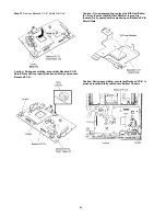
Step 1 Remove Top Cabinet.
Step 2 Remove SMPS P.C.B..
Step 3 Position SMPS P.C.B. on the insulated material.
Step 4 Connect 12P cable at the connector (CN100) on Main
P.C.B..
Step 5 Proceed to check and repair SMPS P.C.B..
11.4. Checking & Repairing of Panel
P.C.B.
Step 1 Remove Top Cabinet.
Step 2 Remove Panel P.C.B & Power Button P.C.B.
Step 3 Position Panel P.C.B & Power Button P.C.B on the insu-
lated material as diagram shown.
Step 4 Connect 17P FFC at the connector (CN203) on Main
P.C.B..
Step 5 Proceed to check and repair Panel P.C.B..
11.5. Checking & Repairing of DVD
Module P.C.B.
11.5.1.
Checking & Repairing of Backend
P.C.B. (Side B)
Step 1 Remove Top Cabinet.
Step 2 Remove Backend P.C.B. Shield Plate Unit.
Step 3 Proceed to check & repair side B of Backend P.C.B..
Содержание SA-XH50P
Страница 13: ...13 4 1 Others Licences ...
Страница 14: ...14 5 Location of Controls and Components 5 1 Remote Control and Main Unit Key Button Operations ...
Страница 16: ...16 5 4 Speaker Connection ...
Страница 17: ...17 5 5 Linked Operations with the TV VIERA LINK HDAVI Control ...
Страница 18: ...18 ...
Страница 19: ...19 5 6 Connection with an ARC compatible TV ...
Страница 21: ...21 5 7 2 File Extension Type Support MP3 JPEG ...
Страница 23: ...23 3 Gently pull out the tray 4 Remove disc ...
Страница 46: ...46 10 2 Main Components and P C B Locations ...
Страница 82: ...82 ...
Страница 92: ...92 ...
Страница 94: ...94 ...
Страница 131: ...131 MMH1104 SFT1 RFKZXH150PK2 50P FFC MAIN TO BACKEND 1 Safety Ref No Part No Part Name Description Qty Remarks ...

