69
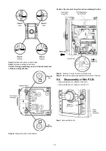
Step 4 Install the Thrust Spring.
Step 5 Install the Winding Lever.
Caution 1: Ensure that the Winding Arm Ass’y is pulled
towards to the right as arrow shown to enable full insertion
of the Winding Lever. The Winding Lever must be seated
on the Main Gear as diagram shown.
Caution 2: Ensure that the Winding Lever is firmly inserted
and properly catched on the tape side as diagram shown.
Содержание SA-VK480EE
Страница 12: ...12 ...
Страница 41: ...41 7 1 3 2 D Amp P C B Figure 3 D Amp P C B Audio Digital Power Amp IC IC5000 D Amp P C B SPEAKER OUTPUT ...
Страница 43: ...43 7 1 3 4 D Amp IC Configuration Figure 5 VK480EE Pin 10 Front Right IC5000 Pin 14 Front Left ...
Страница 47: ...47 ...
Страница 49: ...49 9 2 Main Components and P C B Location ...
Страница 104: ...104 ...
Страница 114: ...114 ...
Страница 116: ...116 ...
Страница 142: ...142 ...


