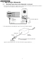
1 Use of Active Subwoofer
4
1.1.
Checking Player when Active Subwoofer is not used
4
2 Safety Precautions
5
2.1.
GENERAL GUIDELINES
5
3 Prevention of Electro Static Discharge (ESD) to
Electrostatically Sensitive (ES) Devices
5
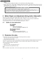
4 Before Repair and Adjustment (Using Active Subwoofer)
6
4.1.
Caution for fuse replacement
6
5 Protection Circuitry
6
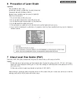
6 Precaution of Laser Diode
7
7 About Lead Free Solder (PbF)
7
8 General Description
8
8.1.
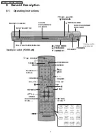
Operating instructions
8
8.2.
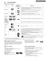
Disc information
9
8.3.
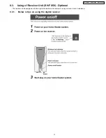
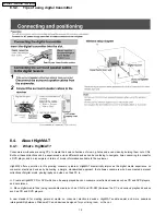
Using of Receiver Unit (SH-FX50) - Optional
11
8.4.
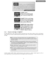
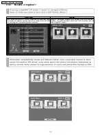
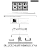
About HighMAT
12
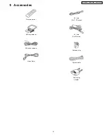
9 Accessories
17
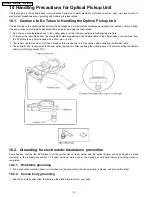
10 Handling Precautions for Optical Pickup Unit
18
10.1. Cautions to Be Taken in Handling the Optical Pickup Unit
18
10.2. Grounding for electrostatic breakdown prevention
18
11 Disassembly and Main Component Replacement Procedures
20
11.1. Disassembling the Top Cabinet
21
11.2. Disassembling the Front Panel
21
11.3. Disassembling the Tray Assembly
21
11.4. Disassembling the Mechanism Base Block
22
11.5. Disassembling the Main P.C.B
22
11.6. Removal of the Tray Base Guide (L) and Tray Base Guide
(R)
23
11.7. Removal of the Rotary Tray
23
11.8. Removal of the Open Lock Gear
23
11.9. Removal of the Close Lock Gear
23
11.10. Removal of the Tray Motor P.C.B. and Sensor P.C.B.
24
11.11. Removal of the CD Traverse Unit
24
11.12. Removal of the Pulley Gear
24
11.13. Removal of the Loading Motor P.C.B.
25
11.14. Removal of the Drive Gear (A) & (B)
25
11.15. Disassembling the Fixed Plate, Magnet and Clamper
25
11.16. Removal of the Cam Gear & Support Piece
26
11.17. Removal of the Slide Plate (L) & (R) and Change Lever 26
11.18. Assembly of Tray Base
27
12 Service Position
28
12.1. Checking, Repair Tray Motor P.C.B and Sensor P.C.B 28
12.2. Checking, Repair Main P.C.B
28
12.3. Checking, Repair DVD Module P.C.B
28
13 DVD-Optical Pick-up Self-Diagnosis and Replacement
Procedure
29
13.1. Optical Pickup Breakdown Diagnosis
29
13.2. Service Mode Table 1
30
13.3. DVD Self Diagnostic Function-Error Code
30
13.4. Service mode table 2
32
13.5. Sales demonstration lock function
34
13.6. Handling After Completing Repairs
34
14 Self-Diagnosis Function
35
14.1. Automatic Displayed Error Codes
35
14.2. Memorized Error Codes
35
15 Service Precautions
36
15.1. Recovery after the DVD player is repaired
36
15.2. Firmware version-up of the DVD player
36
16 Adjustment Procedure
37
16.1. Service Tools and Equipment
37
16.2. Important points in adjustment
37
16.3. Storing and handling of test discs
37
16.4. Optical adjustment
38
17 Abbreviations
39
18 Voltage Chart
41
18.1. DVD Module P.C.B.
41
18.2. Main P.C.B.
4
2
18.3. FL P.C.B.
4
3
18.4. Loading Motor P.C.B., Tray Motor P.C.B., Sensor P.C.B.
4
3
19 Wave Form Chart
4
4
20 Schematic Diagram Notes
4
5
21 Block Diagram
47
22 Schematic Diagram
53
23 Printed Circuit Board Diagram
63
24 Wiring Connection Diagram
67
25 Illustration of IC
痴
, Transistors and Diodes
69
26 Terminal Function of ICs
70
26.1. IC2018 (MN101C49GHB): Operation CPU
70
27 Parts Location and Replacement Parts List
71
27.1. Loading Mechanism, Traverse Unit & Cabinet
72
27.2. Component Parts List
76
27.3. Packing Materials & Accessories Parts List
86
27.4. Packaging
86
CONTENTS
Page
Page
3
SA-HT930P / SA-HT930PC / SA-HT930PX
Содержание SA-HT930P
Страница 10: ...10 SA HT930P SA HT930PC SA HT930PX ...
Страница 19: ...19 SA HT930P SA HT930PC SA HT930PX ...
Страница 33: ...33 SA HT930P SA HT930PC SA HT930PX ...
Страница 46: ...46 SA HT930P SA HT930PC SA HT930PX ...
Страница 52: ...SA HT930P SA HT930PC SA HT930PX 52 ...
Страница 62: ...SA HT930P SA HT930PC SA HT930PX 62 ...
Страница 68: ...SA HT930P SA HT930PC SA HT930PX 68 ...
Страница 73: ...73 SA HT930P SA HT930PC SA HT930PX ...
Страница 74: ...74 SA HT930P SA HT930PC SA HT930PX ...


