background image

 3

1  Safety Precautions 

1.1.   General Guidelines

     1. IMPORTANT SAFETY NOTICE

    There are special components used in this equipment which are important for safety. These parts are marked by    in the 

Schematic Diagrams, Circuit Board Layout, Exploded Views and Replacement Parts List. It is essential that these critical 

parts should be replaced with manufacturer’s specified parts to prevent X-RADIATION, shock, fire, or other hazards. Do not 

modify the original design without permission of manufacturer.

 2.An Isolation Transformer should always be used     during the servicing of AC Adaptor whose chassis is not isolated from 

the AC power line. Use a transformer of adequate power rating as this protects the technician from accidents resulting in 

personal injury from electrical shocks. It will also protect AC Adaptor from being damaged by accidental shorting that may 

occur during servicing.

 3.When servicing, observe the original lead dress. If a short circuit is found, replace all parts which have been overheated or 

damaged by the short circuit.

 4.After servicing, see to it that all the protective devices such as insulation barriers, insulation papers shields are properly 

installed.

 5. After servicing, make the following leakage current checks to prevent the customer from being exposed to shock hazards.

1.2.   Leakage Current Cold Check


1.Unplug the AC cord and connect a jumper between the two prongs on the plug.

 2.Measure the resistance value, with an ohmmeter, between the jumpered AC plug and each exposed metallic cabinet part onthe 

equipment such as screwheads, connectors, control shafts, etc. When the exposed metallic part has a return path to thechassis, 

the reading should be between 1 MΩ and 5.2 MΩ. When the exposed metal does not have a return path to the chas-sis, the 

reading must be infinity.

1.3.   Leakage Current Hot Check (See Figure. 1)

 1.Plug the AC cord directly into the AC outlet. Do not use an isolation transformer for this check.

 2.Connect a 1.5 kΩ, 10 W resistor, in parallel with a 0.15 μF capacitor, between each exposed metallic part on the set and a 

good earth ground, as shown in Figure. 1.

 3.Use an AC voltmeter, with 1 kΩ/V or more sensitivity, to measure the potential across the resistor.

 4.Check each exposed metallic part, and measure the voltage at each point.

 5.Reverse the AC plug in the AC outlet and repeat each of the above measurements.

 6.The potential at any point should not exceed 0.75 V RMS. A leakage current tester (Simpson Model 229 or equivalent) 

maybe used to make the hot checks, leakage current must not exceed 1/2 mA. In case a measurement is outside of the 

limitsspecified, there is a possibility of a shock hazard, and the equipment should be repaired and rechecked before it is 

returned tothe customer.

1.4.   Protection Circuitry

The protection circuitry may have operated if either of the following conditions are noticed:

  •No sound is heard when the power is turned on.

  •Sound stops during a performance.

The function of this circuitry is to prevent circuitry damage if, for example, the positive and negative speaker connection wires 

are“shorted”, or if speaker systems with an impedance less than the indicated rated impedance of the amplifier are used.If this 

occurs, follow the procedure outlines below:

     1.Turn off the power.

     2.Determine the cause of the problem and correct it.

     3.Turn on the power once again after one minute.

Note:

     When the protection circuitry functions, the unit will not operate unless the power is first turned off and then on again.

3

Figure. 1 

Содержание SA-BTT405P

Страница 1: ...s in attempting to service a product Products powered by electricity should be serviced or repaired only by experienced professional technicians Any attempt to service or repair the product or products dealt with in this service information by anyone else could result in serious injury or death WARNING Panasonic Corporation 2014 Unauthorized copying and distribution is a violation of law SB HFS401...

Страница 2: ... cannot be ejected by the OPEN CLOSE button 15 8 Multiple Pressing Function 16 8 1 About the Multiple Pressing of the Unit s Remote Control 16 8 2 How to enter the Special Modes using the Multiple Pressing Function of the Unit s Remote Control 16 9 Service Mode 19 9 1 About the Service Mode 19 9 2 Service Mode List 20 9 3 Self Diagnostics Functions 21 10 Troubleshooting Guide 22 10 1 About Operati...

Страница 3: ...echassis the reading should be between 1 MΩ and 5 2 MΩ When the exposed metal does not have a return path to the chas sis the reading must be infinity 1 3 Leakage Current Hot Check See Figure 1 1 Plug the AC cord directly into the AC outlet Do not use an isolation transformer for this check 2 Connect a 1 5 kΩ 10 W resistor in parallel with a 0 15 μF capacitor between each exposed metallic part on ...

Страница 4: ...plying power to the unit under test 2 After removing an electrical assembly equipped with ES devices place the assembly on a conductive surface such as aluminum foil to prevent electrostatic charge buildup or exposure of the assembly 3 Use only a grounded tip soldering iron to solder or unsolder ES devices 4 Use only an antistatic solder removal device Some solder removal devices not classified as...

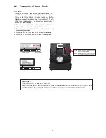
Страница 5: ...ted from the pick up lens Wave length 770 to 800 nm CDs 645 to 660 nm DVDs Maximum output radiation power from pick up 100 μW VDE Laser radiation from the pick up lens is safety level but be sure the followings 1 Do not disassemble the optical pick up unit since radiation from exposed laser diode is dangerous 2 Do not adjust the variable resistor on the pick up unit it was already adjusted 3 Do no...

Страница 6: ...ity of the working environment Repair in the working environment that is grounded 2 4 1 Work table grounding Put a conductive material sheet or steel sheet on the area where the traverse unit optical pick up is placed and ground the sheet 2 4 2 Human body grounding Use the anti static wrist strap to discharge the static electricity from your body 2 4 3 When exchanging the Drive Before remove the E...

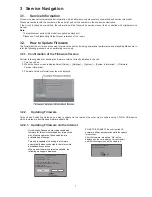
Страница 7: ...connection When a new firmware version is available the following message is displayed DO NOT DISCONNECT the unit from the AC power or perform any operation while the update is in process After the firmware is installed FIn will be displayed on the unit s display Unit will restart and the following screen will be displayed Firmware Update Current Version X XX New Version X XX Do you want to start ...

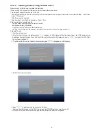
Страница 8: ... to root diretory of the USB device If using CD R instead of USB device burn the file to a blank CD R by a writing software 3 Update the unit 1 Tunr the unit power on 2 After the home screen is displayed and appears at LED display of the front panel insert the USB device stored downloaded latest firmware file to the front USB port of the unit LED display change to or insert the CD R into the unit ...

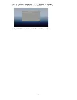
Страница 9: ...he firmware update is complete is displayed at LED display Remove the USB device or the CD R and press the POWER button to turn the unit off 6 Turn the unit on and the home screen appears the firmware update is completed 9 ...

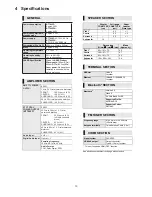
Страница 10: ... 790 nm CDs 658 nm DVDs 405 nm BDs Laser power No hazardous radiation is emitted with the safety protection AMPLIFIER SECTION RMS TTL POWER OUTPUT BTT465 1000 W 1 kHz 30 total harmonic distortion FRONT CENTRE SURROUND 167 W per ch 4 167 W 4 167 W per ch 4 55 Hz 30 total harmonic distortion SUBWOOFER 167 W 4 RMS TTL POWER OUTPUT BTT405 600 W 1 kHz 30 total harmonic distortion FRONT CENTRE SURROUND ...

Страница 11: ... 0 and or LGPL V2 1 The software categorized as 3 5 are distributed in the hope that it will be useful but WITHOUT ANY WARRANTY without even the implied warranty of MERCHANTABILITY or FITNESS FOR A PARTICULAR PURPOSE Please refer to the detailed terms and conditions thereof shown in the Settings menu At least three 3 years from delivery of this product Panasonic will give to any third party who co...

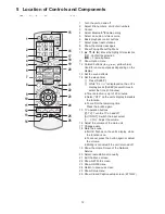
Страница 12: ...veral times to select the time in minutes p Timer selection is up to 120 minutes p Select OFF on the unit s display to disable the function p To confirm the remaining time Press the button again 15 TV operation buttons TV Turn the TV on and off AV INPUT Switch the input select K L VOL Adjust the volume 16 Adjust the volume of the main unit 17 Change audio 18 18 Mute the sound p MUtE flashes on the...

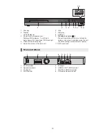
Страница 13: ...unit 6 Stop 7 Start play 8 USB port 9 Standby on switch I Press to switch the unit from on to standby mode or vice versa In standby mode the unit is still consuming a small amount of power 10 NFC touch area 1 AC IN terminal 2 Speaker terminals 3 Cooling fan 4 AUX terminal 5 LAN port 6 HDMI AV OUT ARC terminal 7 DIGITAL AUDIO IN terminal 8 FM radio antenna terminal Main unit Front 4 2 3 1 5 6 7 8 9...

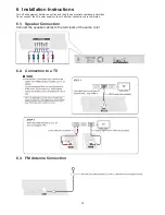
Страница 14: ...tion and read the appropriate operating instructions Do not connect the AC power supply cord until all other connections are completed 6 1 Speaker Connection Connect the speaker cables to the terminals of the same color 6 2 Connection to a TV 6 3 FM Antenna Connection ...

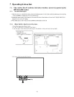
Страница 15: ...1 1 Forcible Disc Eject 7 1 2 When the Disc Eject can not be done 1 Turn off the power and pull out AC cord 2 Put the unit upside down so that bottom can be seen 3 Insert the paper clip into the slot and slide the gear in the direction of the arrow to eject the tray slightly 4 Pull the unit upward and pull out the tray Tray ...

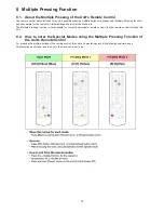
Страница 16: ...each of the following special modes After entering each mode and then go to the menu you want to run 16 8 Multiple Pressing Function 8 1 About the Multiple Pressing of the Unit s Remote Control The remote control which included this unit is possible pressing multiple buttons simultaneously Multiple Pressing function and can operate for the customer s initial settings and the Service Mode etc The M...

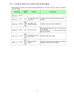
Страница 17: ...17 8 2 1 Open Mode Remote Cont Buttons OK Yellow Blue 17 8 2 1 Open Mode Remote Cont Buttons OK Yellow Blue ...

Страница 18: ...3 Privately Mode 2 Remote Cont Buttons 5 9 Red 18 8 2 2 Privately Mode 1 Remote Cont Buttons 6 7 Yellow 8 2 3 Privately Mode 2 Remote Cont Buttons 5 9 Red 18 8 2 2 Privately Mode 1 Remote Cont Buttons 6 7 Yellow 8 2 3 Privately Mode 2 Remote Cont Buttons 5 9 Red ...

Страница 19: ... Informations necessary for service can be displayed 9 1 1 How to enter the Service Mode 9 1 2 How to exit the Service Mode Press and hold the Power button remote control or unit The Service Mode is terminated and automatically turns the unit off ...

Страница 20: ...20 9 2 Service Mode List The display of information to each command is as follows Note Do not use it excluding the designated command ...

Страница 21: ...service personnel by Self Diagnosis Display when any error has occurred U H and F are stored in memory and held You can check last error code by transmitting 0 1 of Remote Control in Service Mode Automatic Display on FL will be cancelled when the power is turned off or AC input is turned off during self diagnosis display is ON ...

Страница 22: ...22 10 Troubleshooting Guide 10 1 About Operation of Set The page number in this chapter does not show the page number of this service manual ...

Страница 23: ...y To show the firmware version on this unit 32 Firmware Version Information Downloading will require several minutes It may take longer or may not work properly depending on the connection environment If you do not want to check for the latest firmware version set Automatic Update Check to Off 32 l Symbols Encryption Key Password Shift Delete Finish Alphanumeric Other Characters OK RETURN PVGT ECU...

Страница 24: ...eck the Front Panel Broken etc OK Exchange the Check AC inlet unit cutting or damage etc OK NG Exchange the AC inlet unit Exchange Front Panel NG Check the Digital P C B connector voltage 1 Check the Digital P C B connector voltage 2 Exchange the Power supply P C B Exchange the Digital P C B Exchange the Front P C B NG Check the Digital P C B connector XP4 voltage 3 Exchange the Mechanism unit OK ...

Страница 25: ...ont P C B NG NG NG NG Check the Front Panel Broken etc OK Exchange the let unit age etc NG Exchange the AC inlet unt Exchange Front Panel NG he connector 1 e B connector 2 Exchange the Power supply P C B Exchange the Digital P C B Front P C B NG Check the Digital P C B connector XP4 voltage 3 Exchange the Mechanism unit OK NG NG Exchange the Digital P C B FFC Exchange the FFC NG 3 CHECK POINT LOCA...

Страница 26: ...eck the Digital P C B connector XP9 voltage 2 NG Exchange the Digital P C B OK Exchange the Check the battery of the Remote Control Exchange the Front P C B 2 VOLTAGE DATA measurement value CHECK POINT LOCATION REF NO PIN NO XP9 1 3 3V 2 3 3V 3 1 7V 4 PIO9 5 PIO11 6 PIO13 7 GND 8 3 3V 9 GND 10 3 3V 11 0V 12 0V 13 3 3V 14 3 3V 15 3 3V 16 3 3V 17 3 3V 18 11 9V 19 GND 20 BT_L 21 GND 22 BT_R 23 GND 24...

Страница 27: ...e the Digital P C B OK Exchange the Check the battery of the Remote Control Exchange the Front P C B 2 CHECK POINT LOCATION REF NO PIN NO XP9 1 3 3V 2 3 3V 3 1 7V 4 PIO9 5 PIO11 6 PIO13 7 GND 8 3 3V 9 GND 10 3 3V 11 0V 12 0V 13 3 3V 14 3 3V 15 3 3V 16 3 3V 17 3 3V 18 11 9V 19 GND 20 BT_L 21 GND 22 BT_R 23 GND 24 NFC_FD VOLTAGE DATA measurement value 24 2 ...

Страница 28: ... OK Check the Setup of HOME menu NG Setup Deepclolor and Progressive off c Check the Connection NG reconnect correctly OK OK NG Exchange the Speaker Box Check the Speaker Box NG Progressive off c OK Check the HDMI Cable NG Exchange the HDMI Cable OK NG Exchange the fan OK Check the Fan Operation OK Exchange theDigital P C B OK Exchange the Digital P C B Exchange theDigital P C B c ...

Страница 29: ...Check the NFC P C B Front PCB Connetor 4 Voltage waveform d Exchange the NFC P C B NG OK NG Exchange the FFC NG Exchange the FFC Check the FFC Check the FFC OK Exchange the FFC OK Check the Front P C B NG Exchange the Front P C B OK Check the Front P C B NG Exchange the Front P C B OK Exchange the Digital P C B Check the FFC OK Exchange the Digital P C B Exchange the Digital P C B 4 FFC CHECK POIN...

Страница 30: ... OK NG Exchange the Mechanism unit Change to other discs and try playback again OK Exchange the Digital P C B Symptom 10 Fan does not work Set the VOL to 100 Fan is OK Set the VOL to 100 NG OK Fan is OK Check the voltage of XP29 1 11V OK Exchange the fan Check the voltage of XP29 1 11V OK NG Exchange the fan Exchange the Digital P C B ...

Страница 31: ...ANISM MPEG DECODER MT8561 MOTOR DRIVER TPIC2060 A DDR3 1GbX1 2GbX1 C t l XP5 XP6 XS1 ER ay 1 4 4 1 1 KEY 6 1 5 _ TPIC_A PIO11 PIO13 GND BT_3V3 GND 3 3V_STBY_MCU V CLK MECHANISM UNIT A FLASH 2Gb 2GbX1 ADC CE C Crystal 12M 9 1 LED DRIVER LED Display 9 V_CLK V_DATA V_STB IR_IN POWER TPIC_LOAD PLAY PAUSE TPIC_LOAD OPEN CLOSE FLASH 2Gb ADC CE C MCU STM08S005C6 Source Switch2 74HC4052 XP4 XP9 XP1 USB IR...

Страница 32: ...0V 2 GND 4 PIN NO VALUE 1 See Fig 2 2 GND 3 GND 4 GND 5 25 6V 6 25 6V 7 25 6V 5 PIN NO VALUE 1 5 1V 2 0V 3 0V 4 GND 6 PIN NO VALUE 1 3 3V 2 3 3V 3 1 7V 4 5 6 7 GND 8 3 4V 9 GND 10 3 4V 11 0V 12 0V 13 3 3V 14 3 4V 15 3 4V 16 3 4V 17 3 4V 18 11 9V 19 GND 20 21 GND 22 23 24 7 PIN NO VALUE 1 See Fig 3 2 GND 24 XP5 XP4 XP3 XP7 XP29 1 7 XP6 XP9 ...

Страница 33: ... Flow Chart The following chart is the procedure of disassembling the casing and inside parts for internal inspection when carrying out the servicing To assemble the unit reverse the steps shown in the chart below Digital P C B Power Supply P C B Mechanism Unit Front P C B NFC P C B ...

Страница 34: ... paper clips etc into the hole on the bottom of the main unit and slide the lever in the direction of 1 to eject the disc tray slightly 2 Unlock 2 tabs turn Pull the Tray Ornament in direction of 2 12 3 2 2 Front Panel Unit 1 Detach the lead wires fixed at hooking part of the Body Chassis 2 Remove the connector A and flex A 3 Unlock 5 tabs A E turn Pull with the Front Panel Unit in the direction o...

Страница 35: ...tor A and B 2 Remove the 2 screws A then remove the Power Supply P C B Unit Screw A Screw A Body Chassis Hooking part 12 3 4 Body Chassis 1 Detach the lead wires fixed at hooking part of the Body Chassis 2 Remove 3 Screws A to remove the Body Chassis 13 3 5 Power Supply P C B Unit 1 Disconnect the connector A and connect B 2 Remove the 4 screws A then remove the Power Supply P C B Unit Connector A...

Страница 36: ...recton of 1 12 3 7 Digital P C B Unit 1 Remove the 4 screws A and screw B 2 Remove the connector A and flex A 3 Remove the flex B and isolate it with an ESD prevention bag RPFC0114 4 Remove the 3 screws C and remove the Digital P C B Unit 38 12 3 6 Fan Motor Unit 1 Remove the 2 screws A 2 Remove the 2 screws A then remove the Fan Motor Unit in directon of 1 12 3 7 Digital P C B Unit 1 Remove the 4...

Страница 37: ...an Motor 12 3 7 Digital P C B Unit 1 Remove the 4 screws A and screw B 2 Remove the connector A and flex A 3 Remove the flex B and isolate it with an ESD prevention bag RPFC0114 4 Remove the 3 screws C and remove the Digital P C B Unit 12 3 9 AC Inlet Unit 1 Press tab A on the AC cord connector simultaneously in the direction of arrows to pull the AC cord out from the Back Panel AC Inlet Unit Tab ...

Страница 38: ...ware for Web camera and the software for the code writing to Digital P C B Note The adjustment software can be downloaded from Support Information from NWBG VDBG AVC web site in TSN system together with instructions of Adjustment Software including preparations and connections etc No Part No Uses Pcs Compatibility 1 RFKZ0139 Serial Card PC Main Unit for using PC method 1 Same as previous model 2 R...

Страница 39: ...Connect the serial card to 4 pin serial port connector on the Digital P C B Unit via 6p 4p conversion cable RFKZ0602 4 Click file name Rpower_2 9 71 KEM480 _for Pana and Execute Adjustment Software FERpower exe on PC 5 Set ComPort matching to the available PC Port No 6 Execute QR Reader software 7 After staring up select ALL from the pull down menu ...

Страница 40: ...ism Unit bottom side 10 Turn on the Main Unit 11 Select QR code and copy by using CTRL C and then paste to Bar Code field by using CTRL V Then click Write F2 button 12 Check PASS is lit green then it s OK PASS is displayed about 1 second Don t miss PASS display ...

Страница 41: ... adjustment is completed 13 1 3 Using Remote control Method Perform the Step 6 to Step 10 of 13 1 2 Using PC Method to read QR code of Mechanism Unit Or read QR code using smartphone s QR code reader 1 Connect the Main Unit to TV then turn the Main Unit on 2 After start up make the Main Unit go to the Setting UI using Remote Control 3 Press 5 1 7 7 OK key of Remote Control the FA mode screen is di...

Страница 42: ...ey to decide and enter selected character If entering 64 character of barcode finished press RETURN key to finish key in then press OK key to save inputs To Cancel Adjustment Return to Settings Screen Press STOP key 7 When the drive adjustment is completed Pass is displayed Press STOP key twice the screen is return to Settings screen If the drive adjustment is failed Fail is displayed ...

Страница 43: ... device then tap Security to open the Security screen 2 Tap the of Unknown sources 3 Confirming message is displayed tap OK Checkmark is added to Unknown sources No Part No Uses Pcs Compatibility 1 NFC compatible Android device 1 Android 4 1 or higher Preparation Download NFC tag writer software TCL BT TAG writerV1 4 apk from Support Information from NWBG VDBG AVC web site in TSN system then send ...

Страница 44: ...p APK file of NFC tag writing software which received to install 5 Tap Install then tap Done 6 Open the Settings screen of Android device again then tap Security to open the Security screen 7 Tap the of Unknown sources to clear the checkmark TCL BT TAG writer V1 4 apk 4 Tap APK file of NFC tag writing software which received to install 5 Tap Install then tap Done 6 Open the Settings screen of Andr...

Страница 45: ...t of 40 ef 4c in MAC ADDRESS column the 6 digits numbers are printed on the label which pasted on the Bluetooth module of Front P C B and the will appear automatically when you input DEVICE NAME will appear automatically but you also can delete it and input Panasonic BTT Once you do it after Tag writer software has been installed the default device name always displayed as Panasonic BTT 5 Tap Writ...

Страница 46: ...ersion Then version up is not necessary 4 Transfer 9 9 in the service mode setting and initialize the service settings return various settings and error information to their default values The laser time is not included in this initialization Make sure that CLR appears on the LED display After checking it turn the power off 5 After replacing the Mechanism Unit transfer 9 5 in the service mode sett...

Страница 47: ...03 RHD30210 BLACK SCREW 1 104 RHD30210 BLACK SCREW 1 105 RHD30210 BLACK SCREW 1 106 RHD30210 BLACK SCREW 1 121 RHD30211 SILVER SCREW A 1 141 RHD26077 SILVER SCREW B 1 142 RHD26077 SILVER SCREW B 1 Safety Ref No Part No Part Name Description Pcs Remarks 143 RHD26077 SILVER SCREW B 1 144 RHD26077 SILVER SCREW B 1 145 RHD26077 SILVER SCREW B 1 161 RHD40041 SILVER SCREW C 1 162 RHD40041 SILVER SCREW C...

Страница 48: ...Parts Mechanism Section 1 2 3 4 5 6 7 8 9 10 11 12 13 14 15 16 17 18 101 102 103 104 105 106 121 141 142 143 144 145 161 162 181 182 183 184 185 186 187 188 189 190 191 192 193 194 195 196 197 21 22 19 20 a a b b c c ...

Страница 49: ... INDOOR ANTENNA BATTERIES NOT SUPPLIED ACCESSORIES BAG Speaker Connection Cables A4 AC CORD SC BTT405 A1 Remote Control P3 P2 P1 P4 Mirror Bag SB HW4010 SB HFS4010 SB HFS4010 SB HC4010 A7 SPEAKER STICKERS PLUG ADAPTOR A6 A8 HDMI CABLE FOR PH ONLY A4 AC CORD FOR P ONLY FOR PH ONLY ...

Отзывы: