36
37
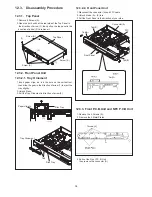
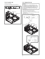
12.3.7. Digital P.C.B.Unit
1. Remove the 4 Screws (A).and Screw (B).
2. Disconnect 2 FFC cabels and connector (A)
.
3. Remove the FFC (B), and isolate it with an ESD prevention
bag (RPFC0114).
4. Remove the 3 Screws (C) to remove it.
Digital P.C.B.
Screw (C)
FFC(A)
Connector(A)
FFC(B)
Screw (C)
12.3.6. Fan Motor Unit
1. Remove 2 Screws (A).
2. Then remove the Fan Motor Unit in directon of (1).
Screw (A)
Fan Motor Unit
Connector (A)
38
12.3.6. Fan Motor Unit
1. Remove the 2 screws (A).
2. Remove the 2 screws (A), then remove the Fan Motor
Unit in directon of (1).
12.3.7. Digital P.C.B. Unit
1. Remove the 4 screws (A) and screw (B).
2. Remove the connector (A) and flex (A).
3. Remove the flex (B), and isolate it with an ESD
prevention bag (RPFC0114).
4. Remove the 3 screws (C) and remove the Digital P.C.B.
Unit.
(1)
39
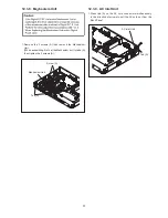
12.3.8. Mechanism Unit
1. Remove the 2 screws (A) then remove the Mechanism
Unit.
(When assembling, first set the Mechanism unit to
tabs (A) then tighten the 2 screws (A).)
12.3.9. AC Inlet Unit
1. Cut the cable tie.
2. Detach the lead wires fixed at hooking part.
3. Remove the Ferrite Core from the cable.
4. Unlock the 2 tabs (A) and remove the AC Inlet Unit.
FFC(B)


