


79
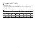
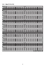
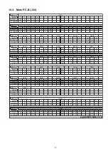
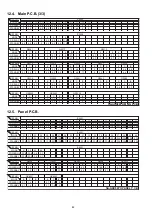
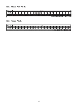
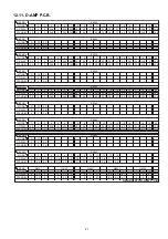
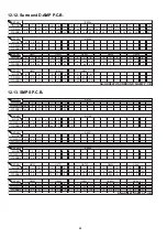
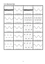
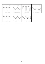
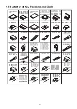
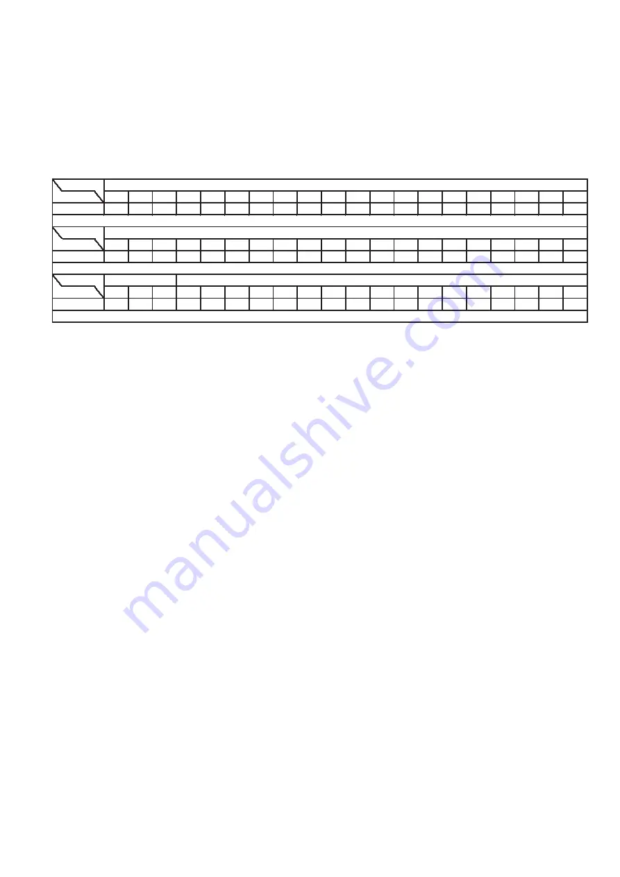
12 Voltage & Waveform Chart
Note:
• Indication Voltage Values are in standard values for the unit measured by the DC electronic circuit tester (high-impedance) with
the chassis taken as standard.
Therefore, there may exist some errors in voltage values, depending on the internal impedance of the DC circuit tester.
• Circuit voltage and waveform described herein shall be regarded as reference information when probing defect point because it
may differ from actual measuring value due to difference of Measuring instrument and its measuring condition and product itself.
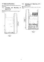
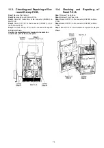
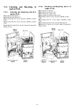
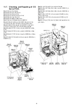
12.1. CD Servo P.C.B.
REF NO.
MODE
1
2
3
4
5
6
7
8
9
10
11
12
13
14
15
16
17
18
19
20
CD PLAY
1.6
0
1.6
0
0
0
0
0
0
7.7
4.4
3.5
3.6
3.6
3.5
3.8
3.7
3.6
7.7
0
REF NO.
MODE
21
22
23
24
25
26
27
28
29
30
CD PLAY
7.7
0
0
0
7.7
1.6
1.6
1.6
0
0
REF NO.
MODE
E
C
B
CD PLAY
3.1
2.0
2.4
IC7002
IC7002
SA-AKX92PH CD SERVO P.C.B.
Q7601
Содержание SA-AKX92PH
Страница 13: ...13 5 Location of Controls and Components 5 1 Main Unit Key Button Operation ...
Страница 14: ...14 5 2 Remote Control Key Button Operation ...
Страница 15: ...15 5 3 Media Information ...
Страница 25: ...25 7 2 2 Main P C B Fig 2 Main P C B Connector ZJ2007 Voltage Regulator IC IC2010 DC DC Converter IC IC2011 ...
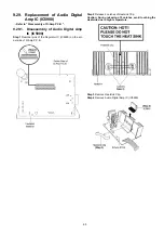
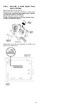
Страница 27: ...27 7 2 4 Surround D Amp P C B Fig 4 Surround D Amp P C B Audio Digital Amp IC IC5900 ...
Страница 33: ...33 9 2 Main Components and P C B Locations ...
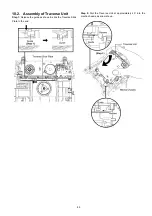
Страница 73: ...73 Step 9 Ground the 24P FFC with a short pin ...
Страница 92: ...92 ...
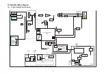
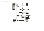
Страница 93: ...93 14 Simplified Block Diagram 14 1 Overall Simplified Block Diagram ...
Страница 104: ...104 ...
Страница 140: ...140 ...
Страница 157: ...157 MMH1103 ...


