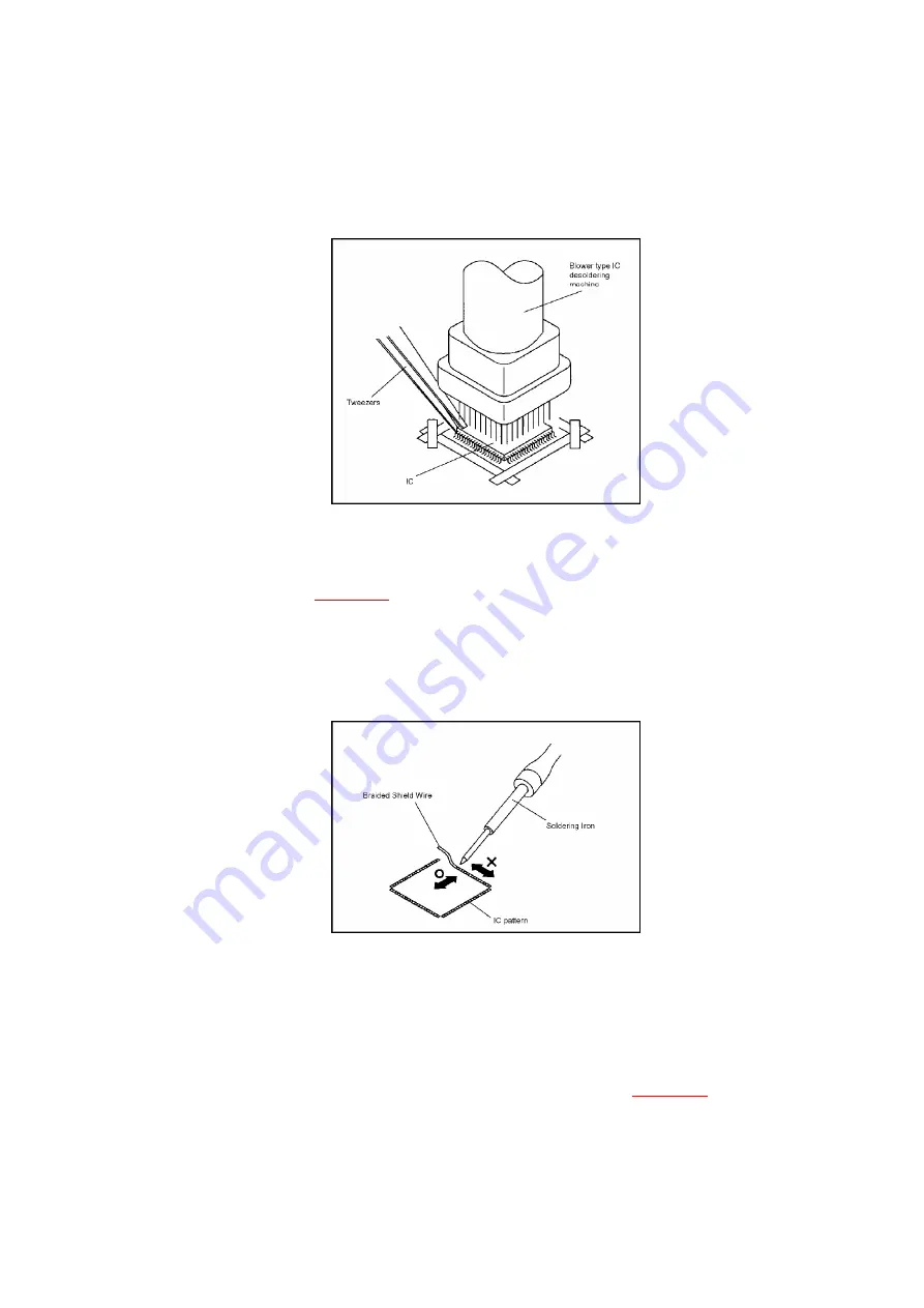
Some ICs on the PCB are affixed with glue, so be careful not to break or damage the foil of each
IC leads or solder lands under the IC when removing it.
Fig. 3-3
4. Peel off the Masking Tape. 4.
5. Absorb the solder left on the pattern using the Braided Shield
Wire. (Refer to
Fig. 3-4
.)
NOTE
Do not move the Braided Shield Wire in the vertical direction towards the IC pattern.
Fig. 3-4
INSTALLATION
1. Take care of the polarity of new IC and then install the new IC
fitting on the printed circuit pattern. Then solder each lead on the
diagonal positions of IC temporarily. (Refer to
Fig. 3-5
.)
Fig. 3-5
26
Содержание PVD734S - DVD/VCR DECK
Страница 46: ...22 2 CHASSIS EXPLODED VIEW TOP VIEW 46 ...
Страница 47: ...22 3 CHASSIS EXPLODED VIEW BOTTOM VIEW 47 ...
Страница 48: ...23 REPLACEMENT PARTS LISTS 23 1 MECHANICAL REPLACEMENT PARTS LIST 48 ...
Страница 54: ...R653 R002T4151J RC 150 OHM 1 4W 54 ...


