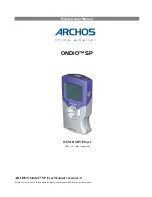
background image

9

Front View of DECK

Audio/Video
Input Connector 2
(LINE 2)

 p. 35

CHANNEL  /

TRACKING/V-LOCK

pp. 21, 6

POWER

PAUSE

p. 23

OPEN/CLOSE

p. 22

VCR/TV

p. 21

STOP/EJECT

p. 20

Multi  Function

Display

p. 11

For  assistance,  call  1-800-211-PANA(7262)

REC

p. 21

If the disc cannot be removed...
First, unplug DECK. Then, prepare a rigid
wire (e.g. an extended paper clip) and,
applying moderate force, insert it straight
into the hole at the base of the tray.
The tray will eject a little. Now, pull the tray
all the way out and remove the disc.

Disc Tray

Over 2 inches

Cassette
Compartment

PLAY

p. 20

Remote

Sensor

FAST FORWARD/SEARCH

p. 20

REWIND/SEARCH

p. 20

Front View of DECK

Initial 

Setup

(Connection)

SKIP 
SKIP 

  p. 23

PLAY

p. 22

STOP

p. 22

Bold:

VCR Function

Italic:

DVD  Function

Bold ItalicVCR and DVD Functions
Normal:

Others

Содержание PVD4742 - DVD/VCR DECK

Страница 1: ...ORDER NO MKE0201800C1 B3 DVD VCR DECK PV D4742 SPECIFICATIONS 1 ...

Страница 2: ...d in this equipment which are important for safety These parts are marked by in the Schematic Diagrams Circuit Board Layout Exploded Views and Replacement Parts List It is essential that these critical parts should be replaced with manufacturer s specified parts to prevent shock fire or other hazards Do not modify the original design without permission of manufacturer 2 An Isolation Transformer sh...

Страница 3: ...NT COLD CHECK 1 Unplug the AC cord and connect a jumper between the two prongs on the plug 2 Measure the resistance value with an ohmmeter between the jumpered AC plug and each exposed metallic cabinet part on the equipment such as screwheads connectors control shafts etc When the exposed metallic part has a return path to the chassis the reading should be between 1 M and 5 2 M When the exposed me...

Страница 4: ...s classified as a Class I Class 1 level LASER Product and there is no hazardous LASER radiation with the safety protection Caution Use of controls or adjustments or performance of procedures other than those specified herein may result in hazardous radiation exposure Danger The serviceman should not remove the cover of drive unit and should not service because the drive unit is a non serviceable p...

Страница 5: ...tate devices can be damaged easily by static electricity Such components commonly are called Electrostatically Sensitive ES Devices Examples of typical ES devices are integrated circuits some field effect transistors and semiconductor chip components The following techniques should be used to help reduce the incidence of component damage caused by electrostatic discharge ESD 1 Immediately before h...

Страница 6: ...and observe all other safety precautions 8 Minimize bodily motions when handling unpackaged replacement ES devices Otherwise harmless motion such as the brushing together of your clothes fabric or the lifting of your foot from a carpeted floor can generate static electricity ESD sufficient to damage an ES device NOTE to CATV system installer This reminder is provided to call the CATV system instal...

Страница 7: ... With power turned off press CH DOWN button on VCR for over 3 seconds if VCR is not in shut off condition Fig 1 1 2 Fault code 3 digit number will be displayed in F I P as shown Fig 1 2 Fig 1 3 Fig 1 4 7 ...

Страница 8: ...R goes into VCR shut off condition Then the VCR stops and all VCR function buttons except for power become non operational 3 Lock data will be cleared at the first power on operation after Lock code is displayed in FIP 4 1 2 USAGE SCREEN MODE Function displayed on the TV monitor the total elapsed Cylinder rotation time in hours the total elapsed DVD Play time in hours 1 With power turned and no ca...

Страница 9: ...SHIFTER ADJUSTMENT in ELECTRICAL ADJUSTMENT procedures 4 1 4 GROUNDING FOR ELECTROSTATIC BREAKDOWN Prevention 1 Human body grounding Use the antistatic wrist strap to discharge the static electricity from your body 2 Work table grounding Put a conductive material sheet or steel sheet on the area where the optical pickup is placed and ground the sheet Caution The static electricity of your clothes ...

Страница 10: ...detects a problem or malfunction within the unit and displays its corresponding Error code on the TV Screen Note If after approx 30 seconds a unit set to DVD mode automatically switches to VCR mode there is likely a problem with the DVD Decoder C B A IC8000 IC8100 IC8200 etc How to enter DVD Self Diagnostic mode 1 Connect a TV Monitor 2 Insert a DVD disc into the DVD Unit 3 Set the unit to DVD mod...

Страница 11: ...ox 1 5 minutes the check results will appear on the TV screen If no error is detected COMPLETED will appear as shown in Fig 5 3 Be sure to press Power OFF to end Then press Power ON again and remove the DVD disc from the Tray Fig 5 3 If some error is detected a 2 digit for Error Code will appear as shown in Fig 5 4 Fig 5 4 Fig 5 5 11 ...

Страница 12: ...lly Note If the tray has still not opened after 3 minutes or Error Indication appears updating was unsuccessful In this case repeat above steps from step 1 6 Remove the Firmware Disc from the tray Then disconnect the AC Plug The tray will not close 7 Connect the AC Plug and turn on the power Then reset all VCR memory Refer to HOW TO RESET ALL MEMORY FUNCTIONS How to update the firmware of DVD Deco...

Страница 13: ...ct the AC Plug and turn on the power Then reset all VCR memory Refer to HOW TO RESET ALL MEMORY FUNCTIONS CAUTION 1 Do not unplug the AC Cord during updating 2 Do not press any buttons during updating 4 1 9 SERVICE POSITION 4 1 9 1 Service Position CAUTION HOT CIRCUIT Primary circuit exists on the Main C B A Use extreme care to prevent accidental shock when servicing 4 1 9 1 1 Service Position 1 F...

Страница 14: ... Tab SW Pins on the foil side of the Main C B A to turn this SW on Fig 7 2 2 2 Place the tape between the Cassette Up Ass y and Main C B A to get a stability 4 1 9 1 3 Service Position 3 In Service Position 3 the DVD Decoder C B A with Extension Cable LSUA0034 X3 and Connector Cable IDE Cable Not supplied can be performed Fig 7 3 1 14 ...

Страница 15: ...ble IDE to the DVD Unit from the DVD Decoder C B A 3 Connect the 3 Extension Cables as follows With Extension Cable LSUA0034 P8001 on the DVD Decoder C B A to P1501 on the Power Supply C B A With Extension Cable LSUA0034 P8002 on the DVD Decoder C B A to P3001 on the Main C B A With Extension Cable LSUA0034 P8003 on the DVD Decoder C B A to P6002 on the Main C B A 4 Place the DVD Unit and DVD Deco...

Страница 16: ...ndition Fig 8 1 The power comes on and the unit goes into service mode In this mode Mechanism movement can be confirmed When removing Cassette Up Ass y it can be confirmed without a cassette To release from this mode press POWER button off or disconnect AC Plug 4 1 12 TRACKING CENTER MODE TRACKING FIX AT CENTER Insert the Cassette tape Set the unit into Service Mode Play back the Cassette tape Pre...

Страница 17: ...stall the Front Panel Ass y as follows 1 Swing the Cassette Door Lid all the way open until the Cassette Door tab clears the Opener Lever 2 Make sure that all locking tabs are aligned properly Then press the Front Panel straight in Fig 9 4 1 14 METHOD FOR LOADING UNLOADING OF MECHANISM 4 1 14 1 Manual Method Turn the Loading Gear clockwise for loading or counterclockwise for unloading using needle...

Страница 18: ... to Portion b CAUTION Before applying DC Power Supply be sure to cut the Motor Leads with a cutter etc Otherwise the Loading Motor Drive IC IC2501 may be damaged Fig 10 2 4 1 14 2 1 WHEN LOADING WITHOUT A CASSETTE When loading without a cassette push Portion a on the Holder Unit of Cassette Up Ass y so that the Lever clear the First Tab and Second Tab Fig 10 3 18 ...

Страница 19: ...e Remove a jammed tape as follows 4 1 15 1 Manual Method When a tape jam is encountered check the tape loading condition and use the following procedure to remove a tape jam Fig 11 1 Method 1 1 Move the Pinch Roller Unit out by unhooking the Pin of Pinch Arm Unit so that the Pinch Roller is separated from the Capstan Rotor Unit shaft Fig 11 2 19 ...

Страница 20: ... Up Ass y out far enough so that it clears the Drive Rack Arm slide the Drive Rack Unit as indicated by the arrow to remove the cassette tape from the Cassette Up Ass y 7 Check the cause of mechanical trouble and repair Fig 11 3 Method 2 1 Rotate Loading Motor counterclockwise with needlenose pliers etc so that the Pinch Roller is separated from the shaft of the Capstan Rotor Unit 2 Perform Step 2...

Страница 21: ... Power Supply be sure to cut the Motor Leads with a cutter etc Otherwise the Loading Motor Drive IC IC2501 may be damaged 2 If loading does not start in approx 2 seconds after DC Power Supply is applied DO NOT continue to apply DC Power Supply Instead perform Manual Method 1 Be sure to cut the Motor Leads with a cutter etc 2 Apply 10 0 V DC Power Supply to the Loading Motor terminals 3 When the Lo...

Страница 22: ...ose chassis is not isolated from the AC power line Use a transformer of adequate power rating as this protects the technician from accidents resulting in personal injury from electrical shocks It will also protect DVD VCR from being damaged by accidental shorting that may occur during servicing Also when troubleshooting the above type of Power Supply Circuit a variable isolation transformer is req...

Страница 23: ...Fig D2 23 ...

Страница 24: ...Top Cover When removing the Top Cover slide it as indicated by the arrow 2 Installation of Front Panel Ass y CAUTION Opener Lever may be damaged when Front Panel Ass y is installed with Cassette Door Lid of Front Panel Ass y and Opener 24 ...

Страница 25: ...e push the 2 Locking Tabs to release Then slide the VCR Chassis Unit Frame to front side Installation of VCR Chassis Unit When installing 2 Screws 460 slide the Holder Unit of the Cassette Up Ass y Refer to WHEN LOADING WITHOUT A CASSETTE in Service Notes to tighten screws Then slide it back to the EJECT Position 4 Installation of Mechanism Chassis and Cassette Up Ass y onto Main C B A A Make sure...

Страница 26: ...he Shield Plate as shown Fig D5 6 Installation of Cassette Up Ass y A Confirm that the Locking Tab under the Cassette Up Ass y is in Hole on the Mechanism Chassis when installing the Cassette Up Ass y Then slide the Cassette Up Ass y towards the back B When installing 2 Screws 502 slide the Holder Unit Refer to WHEN LOADING WITHOUT A CASSETTE in Service Notes to tighten screws Then slide it back t...

Страница 27: ...5 2 1 Disassembly Reassembly Method 5 2 2 Inner Parts Location Fig J1 1 27 ...

Страница 28: ...5 2 3 EJECT Position Confirmation Fig J1 2 28 ...

Страница 29: ...5 2 4 Full Erase Head and Cylinder Unit Fig J2 5 2 4 1 Reassembly Notes 1 After replacing the Cylinder Unit clear the Total elapsed Cylinder rotation time in hours to 0 Refer to USAGE SCREEN MODE in 29 ...

Страница 30: ...gnment of Main Cam Gear Drive Rack Arm and Main Rod A Confirm that the hole on Main Rod is a Through Hole with a hole on chassis B Confirm that the hole on Drive Rack Arm is a Through Hole with a hole on chassis C Install the Main Cam Gear so that the projection of Main Cam Gear is in the upward position as shown Fig J3 2 30 ...

Страница 31: ...ole with a hole on chassis B Confirm that the hole on Intermediate Gear A is aligned with the hole on Lift Gear Fig J3 3 C Install the Intermediate Gear B so that the hole on the Intermediate Gear B is aligned with the hole on the Main Cam Gear Fig J3 4 3 Holes on Main Cam Gear A The EJECT mode Hole on Main Cam Gear should be a Through 31 ...

Страница 32: ...acement part 5 Installation of Main Cam Gear and Main Cam Push Nut A After installing the Support Angle install the Main Cam Push Nut with Needlenose Pliers etc so that it is flush with the chassis There may be some slight scratches on the Shaft of Main Cam Gear when removing the Main Cam Gear In case that the Main Cam Gear can be installed securely without tottering it is fine to use the one If a...

Страница 33: ...Fig J4 1 5 2 6 1 Reassembly Notes 1 Installation of Center Clutch Unit A Fit the Center Clutch Unit into the Changing Gear Fig J4 2 5 2 7 Reel Gear Main Rod and SS Brake Arm Unit Fig J5 1 33 ...

Страница 34: ...1 Alignment of Main Rod and T Loading Arm Unit A Align the Gear on T Loading Arm Unit with Gear of Main Rod Confirm that the Hole on Main Rod is a Through Hole with a hole on chassis Fig J5 2 5 2 8 Capstan Motor Unit Fig J6 34 ...

Страница 35: ...g Arm Unit and S Loading Arm Unit A Install the S Loading Arm Unit onto the chassis B Install the T Loading Arm Unit so that the hole on T Loading Arm Unit is aligned with the hole on S Loading Arm Unit C Confirm that the holes on the S T Loading Arm Unit are Through Holes with hole on chassis Fig J7 2 35 ...

Страница 36: ...5 2 10 T Brake Unit Tension Control Arm Unit T Reel Table S Reel Table and Tension Arm Unit Fig J8 1 5 2 10 1 Reassembly Notes 1 How to distinguish between S Reel Table and T Reel Table Fig J8 2 36 ...

Страница 37: ...5 2 11 Loading Post Base T Unit and Loading Post Base S Unit Fig J9 5 2 12 Opener Piece Drive Rack Arm Pinch Arm Unit P5 Arm Unit and Intermediate Gear A Fig J10 1 37 ...

Страница 38: ...Arm Unit A Rotate the Lift Gear so that Hole A on Lift Gear is a Through Hole with a hole on chassis B Install the Intermediate Gear A so that the hole on Intermediate Gear A is aligned with the hole on Lift Gear C Install the P5 Arm Unit so that it contacts with the tab of chassis Fig J10 2 2 Installation of Opener Piece A Install the Opener Piece so that the slot of the Opener Piece is inserted ...

Страница 39: ...5 2 13 Motor Block Unit Audio Control Head Unit Lift Gear Tension Arm Boss and Cleaner Arm Unit Fig J11 5 3 CASSETTE UP ASSEMBLY SECTION 5 3 1 Top Plate Wiper Arm Unit and Holder Unit Fig K1 1 39 ...

Страница 40: ... of Wiper Arm Unit and Drive Rack Unit A Slide the Drive Rack Unit to the far right as indicated by the arrow B Install the Wiper Arm Unit so that the hole on the Wiper Arm Unit is aligned with the hole on the Drive Rack Unit Fig K1 2 40 ...

Страница 41: ...ve on Side Plate L and R B Insert Holder Unit boss A and B into the grooves as shown in Fig K1 1 C Finally in the EJECT Position confirm that the protrudence on the Wiper Arm Unit is aligned with the indentation on the Drive Rack Unit Fig K1 3 3 Make sure to hook the spring to the Drive Rack Arm of Mechanism chassis 41 ...

Страница 42: ...5 3 2 Opener Lever and Drive Rack Unit Fig K2 6 ADJUSTMENT PROCEDURES 6 1 SERVICE FIXTURES AND TOOLS 6 2 MECHANICAL ADJUSTMENT 6 2 1 CLEANING PROCEDURE FOR THE UPPER CYLINDER UNIT 42 ...

Страница 43: ... Cleaning Stick VFK27 to remove any Ethanol remaining on the cylinder tape path Otherwise tape damage will occur 6 2 2 ADJUSTMENT PROCEDURES 6 2 2 1 BACK TENSION CONFIRMATION Purpose To fine adjust the Back Tension so that the tape runs smoothly with a constant tension Symptom of Misadjustment 1 If the tape tension is less than the specified value the tape cannot come into proper contact with the ...

Страница 44: ... the Brake Pad of Tension Control Arm Unit and the S Reel Table After cleaning the reading of tension measurement is still out of specification replace the Tension Arm Unit and the Tension Control Arm Unit Fig M2 2 Note 1 Be sure that the three probes of the meter are all in solid contact with the tape but not touching any other parts of the mechanism 2 It is recommended that measurements should b...

Страница 45: ...riation of the tracking control circuit Equipment Required Post Adjustment Driver VFK0329 1 Insert the alignment tape 2 Press and hold FF button and CH DOWN buttons on VCR together over 5 seconds in power off condition The power comes on and the unit goes into service mode 3 Play back the alignment tape 4 To enter Tracking center mode press PLAY button in Play back mode TRACKING CENTER will be dis...

Страница 46: ...steps 1 Release the Tracking center mode 2 Press the Tracking Control Up or Down button on remote control Make sure that the envelope waveform remains flat If not readjust P2 and or P3 post heights Fig M3 1 Fig M3 2 7 After adjustment confirm that the tape travels without curling at P2 and P3 posts Fig M3 3 8 To release from Tracking center mode press PLAY or STOP button 6 2 2 2 2 AUDIO CONTROL HE...

Страница 47: ... lower edge of the P4 post Then adjust the screw counterclockwise until the curling is eliminated Fig M4 6 2 2 2 3 AUDIO CONTROL HEAD HEIGHT ADJUSTMENT The height of the Audio Control Head replacement part is preset at the factory Purpose To be sure the tape runs properly along the Control Head Symptom of Misadjustment If the control signal is not properly picked up Servo Operation cannot be achie...

Страница 48: ... the oscilloscope to the audio output jack on the rear side of the deck 2 Play back the 6 kHz Monaural Audio portion of the alignment tape 3 Adjust Black Screw C on the Audio Control Head base so that the output level is at maximum Fig M6 4 Confirm the height of the Audio Control Head is proper If not readjust Black Screws A and B 6 2 2 2 5 AUDIO CONTROL HEAD HORIZONTAL POSITION ADJUSTMENT Purpose...

Страница 49: ...isplayed on the TV monitor 5 Connect the oscilloscope to TP3002 on the Video Signal Process Section of the Main C B A Use TP6205 as a trigger 6 Loosen the Black Screw D and tighten it slightly Set the H Position Adjustment Driver into the Hole A Then slowly turn the fixture either clockwise or counterclockwise so that the envelope is at maximum Fig M7 7 Tighten Black Screw D 8 To release from Trac...

Страница 50: ...5 TV monitor 6 3 2 HOW TO READ THE ADJUSTMENT PROCEDURES Fig E1 6 3 3 DVD LUMINANCE LEVEL ADJUSTMENT Purpose To set the optimum luminance level for DVD Symptom of Misadjustment The picture is too bright or too dark Test Point TP8201 DVD DECODER C B A TP8537 DVD DECODER C B A Adjustment R8299 DVD DECODER C B A R8523 DVD DECODER C B A Specification 1 0 V P P 50 mV P P 50 ...

Страница 51: ...03 on the DVD DECODER C B A 3 Adjust R8299 on the DVD DECODER C B A so that the level A becomes 1 0 V P P 50 mV P P Fig E2 1 4 For model with PROGRESSIVE OUT Playback 100 Full Color Bar on the DVD Test Disc in DVD PLAY Mode 5 Press PROGRESSIVE OUT button on the unit 6 Connect the Oscilloscope to TP8537 on the DVD DECODER C B A and GND TP8203 on the DVD DECODER C B A 7 Adjust R8523 on the DVD DECOD...

Страница 52: ... of Misadjustment May cause Head Switching Noise and or Vertical Jitter Test Point TP3001 Main C B A TP6205 Main C B A Specification T 6 H 0 5 H 0 38 ms 0 03 ms Mode SP Playback Equipment Oscilloscope VHS Alignment Tape VFMS0003H6 TV monitor 1 Insert the VHS Alignment Tape Then turn off the power Enter service mode by pressing and holding FF and CH DOWN buttons on VCR together for more than 5 seco...

Страница 53: ...5 H 0 38 ms 0 03 ms before the start of the vertical sync pulse by pressing CH UP and CH DOWN buttons on the remote control Fig E3 2 5 After adjustment is completed press REC button on the remote control Then COMP will appear on the TV monitor and adjusted value will be written to Memory IC IC6005 Fig E3 3 6 Press STOP button on the remote control to release from EVR PG SHIFTER ADJUSTMENT MODE 6 4...

Страница 54: ...7 SCHEMATIC DIAGRAMS 54 ...

Страница 55: ...GRAMS 7 3 OPERATION SCHEMATIC DIAGRAM 7 4 DVD DECODER SCHEMATIC DIAGRAMS 7 5 INTERCONNECTION SCHEMATIC DIAGRAM 7 6 VOLTAGE CHART 8 CIRCUIT BOARD LAYOUT 8 1 MAIN C B A 8 2 OPERATION C B A 8 3 DVD DECODER C B A 9 BLOCK DIAGRAMS 10 EXPLODED VIEWS 10 1 MECHANISM TOP SECTION 55 ...

Страница 56: ...10 2 MECHANISM BOTTOM SECTION 56 ...

Страница 57: ...10 3 CASSETTE UP COMPARTMENT SECTION 57 ...

Страница 58: ...10 4 CHASSIS FRAME AND CASING PARTS SECTION 58 ...

Страница 59: ...10 5 PACKING PARTS AND ACCESSORIES SECTION 59 ...

Страница 60: ...MENT PARTS LISTS BEFORE REPLACING PARTS READ THE FOLLOWING 11 1 REPLACEMENT NOTES 11 1 1 General Notes 1 Use only original replacement parts To maintain original function and reliability of repaired units use 60 ...

Страница 61: ...ist 5 Parts different in shape or size may be used However only interchangeable parts will be supplied as service replacement parts 6 Parts with mark AVC in the Remarks column are supplied from AVC Others are supplied from MKI 7 Item numbers with capital letter E Example E10 E20 in the Ref No column are shown in the exploded views 8 Parts whose Ref Nos are the same are interchangeable as replaceme...

Страница 62: ...frared Remote Control Unit Ref No 123 replacement part is available as a complete assembly unit only Do not try to disassemble the Infrared Remote Control Unit However the battery cover is available separately as a replacement part 7 Main Cam Push Nut Ref No 414 is not reusable If removed install a new one 11 1 3 Electrical Replacement Notes 1 Unless otherwise specified All resistors are in K 1 00...

Страница 63: ...vailable as a complete assembly unit only 5 EEP ROM IC IC6005 MAIN C B A replacement note After replacing EEP ROM IC IC6005 or MAIN C B A be sure to perform the PG SHIFTER ADJUSTMENT in ELECTRICAL ADJUSTMENT procedures 6 EEP ROM IC IC8001 DVD Decoder C B A replacement note After replacing EEP ROM IC IC6005 or DVD Decoder C B A confirm the Firmware version of DVD using Self Diagnostic function If t...

Страница 64: ...ASTIC 4 38 LSMB0217 CASSETTE DOOR SPRING 4 41 VXPS0389 CENTER CLUTCH UNIT 2 42 VMBS1151 CHANGING GEAR SPRING 2 43 LSDG0114 CHANGING GEAR 2 44 VXLS1091 IDLER ARM UNIT 2 46 LSEM0056 CAPSTAN MOTOR ASS Y 2 47 LSMM0003 MAIN ROD 2 48 LSJW0027 FLEXIBLE FLAT CABLE W OUT PLUG 2 49 VXLS1099 S LOADING ARM UNIT 2 50 VXLS1098 T LOADING ARM UNIT 2 51 LSDG0116 REEL GEAR 2 52 LSDG0111 INTERMEDIATE GEAR B 2 53 LSM...

Страница 65: ...LSGF0046 SHEET HOLDER 4 289 LSMF0071 SHEET NYLON RAYON 4 305 LSMA0558 DVD HOLDER RIGHT 4 306 LSMA0557 DVD HOLDER LEFT 4 311 LSMF0081 SHEET NYLON RAYON 4 312 LMMY0030 HEAT SHEET SI 4 401 VHDS0475 SCREW STEEL 1 405 XTV3 6J TAPPING SCREW STEEL 4 410 VHDS0498 SCREW W WASHER STEEL 1 414 VHNS0070 MAIN CAM PUSH NUT STEEL 1 422 XWGV2D5G WASHER NYLON 2 424 XYC26 CF8 SCREW W WASHER STEEL 4 447 VHDS0310 SCRE...

Страница 66: ...TOOLS Ref No Part No Part Name Description Remarks VFMS0003H6 VHS ALIGNMENT TAPE VFKS0081 GREASE VFK0329 POST ADJUSTMENT DRIVER VFK27 HEAD CLEANING STICK VFK0330 H POSITION ADJUSTMENT DRIVER DVDT S01 DVD TEST DISC AVC LSUA0034 EXTENSION CABLE 11 3 ELECTRICAL REPLACEMENT PARTS LIST PRINTED CIRCUIT BOARD ASSEMBLY Ref No Part No Part Name Description Remarks E10 LSEP2015HA MAIN C B A E S D RTL E20 LS...

Страница 67: ...3101 MN3885S IC LINEAR E S D IC4201 AN3663FBP V IC LINEAR E S D IC4303 UPC4570G IC LINEAR Ref No Part No Part Name Description Remarks IC4304 C0JBAR000292 IC CMOS STANDARD LOGIC E S D IC4304 CD4053BCM IC CMOS STANDARD LOGIC E S D IC4304 C0JBAR000338 IC CMOS STANDARD LOGIC E S D IC6001 MN101D06FPP IC 8BIT MICROCONTROLLER E S D IC6002 B3NAA0000049 PHOTO INTERRUPUTER IC6003 B3NAA0000049 PHOTO INTERRU...

Страница 68: ...07 2SD601A RS TRANSISTOR SI NPN CHIP Q3007 B1ABCF000011 TRANSISTOR SI NPN CHIP Q3008 2SB709A RS TRANSISTOR SI PNP CHIP Q3008 B1ADCF000001 TRANSISTOR SI PNP CHIP Q3009 2SD601A RS TRANSISTOR SI NPN CHIP Q3009 B1ABCF000011 TRANSISTOR SI NPN CHIP Q3011 UNR521200L TRANSISTOR SI NPN CHIP Q3011 B1GBCFLL0012 TRANSISTOR SI NPN CHIP Q3011 MUN5212T1 TRANSISTOR SI NPN CHIP Q3601 2SD601A RS TRANSISTOR SI NPN C...

Страница 69: ... Q4008 B1GBCFJA0006 TRANSISTOR SI NPN CHIP Q4009 UNR521500L TRANSISTOR SI NPN CHIP Q4009 B1GBCFJA0006 TRANSISTOR SI NPN CHIP Q4101 2SD601A RS TRANSISTOR SI NPN CHIP Q4101 B1ABCF000011 TRANSISTOR SI NPN CHIP Q4304 UNR221200L TRANSISTOR SI NPN CHIP Q4304 B1GBCFLL0002 TRANSISTOR SI NPN CHIP Q4305 2SD0601A0L TRANSISTOR SI NPN CHIP Q4305 B1ABCF000011 TRANSISTOR SI NPN CHIP Q6001 2SD1819A RS TRANSISTOR ...

Страница 70: ...DE SI D1010 ERZV10V361CS SUEGE ABSORBER D1010 D4EAA3610001 SURGE ABSORBER D1015 MA2180LA DIODE ZENER 18V D1015 1N4746A T DIODE ZENER 18V D1015 1N4746ARL DIODE ZENER 18V D1016 MA2C165001VT DIODE SI D1016 B0AACK000004 DIODE SI D1016 1SS119 DIODE SI D1051 MA4110N H DIODE ZENER 11V D1080 ERB84 009V1 DIODE SI D1080 EK19V1 DIODE SI D1501 DB105G DIODE SI D1501 B0EBKR000003 DIODE SI D1501 B0EBKR000020 DIO...

Страница 71: ... 7V D3602 RD4 7ESAB DIODE ZENER 4 7V D3603 MA4047 DIODE ZENER 4 7V D3603 B0BA4R600003 DIODE ZENER 4 7V D3603 MTZJT 774 7A DIODE ZENER 4 7V D3603 MTZJT 774 7C DIODE ZENER 4 7V D3603 RD4 7ESAB DIODE ZENER 4 7V D3604 MA4047 DIODE ZENER 4 7V D3604 B0BA4R600003 DIODE ZENER 4 7V D3604 MTZJT 774 7A DIODE ZENER 4 7V D3604 MTZJT 774 7C DIODE ZENER 4 7V D3604 RD4 7ESAB DIODE ZENER 4 7V D3605 MA4047 DIODE ZE...

Страница 72: ...004 ERG2SJ333H METAL OXIDE 2W 33K R1005 ERG1SJ560P METAL OXIDE 1W 56 R1006 ERJ6GEYJ222V MGF CHIP 1 10W 2 2K R1007 ERDS2TJ101 CARBON 1 4W 100 R1008 ERDS2TJ392 CARBON 1 4W 3 9K R1010 ERD25FJ100P CARBON 1 4W 10 R1010 VRESF4FJ100P CARBON 1 4W 10 R1014 ERJ6GEYJ221V MGF CHIP 1 10W 220 R1015 ERJ6GEYJ222V MGF CHIP 1 10W 2 2K R1016 ERJ6GEYJ102V MGF CHIP 1 10W 1K R1017 D1BD2431A016 MGF CHIP 2 43K R1018 D0HD...

Страница 73: ...ERJ6GEYJ561V MGF CHIP 1 10W 560 R3022 ERJ6GEYJ152V MGF CHIP 1 10W 1 5K R3023 ERJ6GEY0R00V MGF CHIP 1 10W 0 R3027 ERJ6GEYJ821V MGF CHIP 1 10W 820 R3029 ERJ6GEYJ125V MGF CHIP 1 10W 1 2M R3030 ERJ6GEYJ104V MGF CHIP 1 10W 100K R3031 ERJ6GEYJ474V MGF CHIP 1 10W 470K R3032 ERJ6GEYJ223V MGF CHIP 1 10W 22K R3033 ERJ6GEYJ392V MGF CHIP 1 10W 3 9K R3034 ERJ6GEYJ121V MGF CHIP 1 10W 120 R3035 ERJ6GEYJ103V MGF ...

Страница 74: ...YJ561V MGF CHIP 1 10W 560 R3624 ERJ6GEYJ561V MGF CHIP 1 10W 560 R3626 ERJ6GEYJ272V MGF CHIP 1 10W 2 7K R3627 ERJ6GEYJ272V MGF CHIP 1 10W 2 7K R3628 ERJ6GEYJ104V MGF CHIP 1 10W 100K R3629 ERJ6GEYJ223V MGF CHIP 1 10W 22K R3630 ERJ6GEYJ104V MGF CHIP 1 10W 100K R3631 ERJ6GEYJ223V MGF CHIP 1 10W 22K R3632 ERJ6GEYJ104V MGF CHIP 1 10W 100K R3633 ERJ6GEYJ273V MGF CHIP 1 10W 27K R3634 ERJ6GEYJ104V MGF CHIP...

Страница 75: ...W 47K R4203 ERJ6GEYJ822V MGF CHIP 1 10W 8 2K R4204 ERJ6GEYJ822V MGF CHIP 1 10W 8 2K R4205 ERJ6GEYJ473V MGF CHIP 1 10W 47K R4206 ERJ6GEYJ473V MGF CHIP 1 10W 47K R4207 ERJ6GEYJ822V MGF CHIP 1 10W 8 2K R4208 ERJ6GEYJ822V MGF CHIP 1 10W 8 2K R4209 ERJ6GEYJ102V MGF CHIP 1 10W 1K R4210 ERJ6GEYJ102V MGF CHIP 1 10W 1K R4213 ERJ6GEYJ223V MGF CHIP 1 10W 22K R4214 ERJ6GEYJ223V MGF CHIP 1 10W 22K R4218 ERJ6GE...

Страница 76: ...F CHIP 1 10W 1K R6027 ERJ6GEYJ101V MGF CHIP 1 10W 100 R6028 ERJ6GEYJ103V MGF CHIP 1 10W 10K R6029 ERJ6GEYJ561V MGF CHIP 1 10W 560 R6030 ERJ6GEYJ102V MGF CHIP 1 10W 1K R6031 ERJ6GEYJ223V MGF CHIP 1 10W 22K R6033 ERDS2TJ681 CARBON 1 4W 680 R6034 ERJ6GEYJ223V MGF CHIP 1 10W 22K R6035 ERJ6GEYJ102V MGF CHIP 1 10W 1K R6036 ERJ6GEYJ223V MGF CHIP 1 10W 22K R6037 ERJ6GEYJ391V MGF CHIP 1 10W 390 R6039 ERJ6G...

Страница 77: ...GF CHIP 1 10W 15K R6236 ERJ6GEYJ562V MGF CHIP 1 10W 5 6K R6237 ERJ6GEYJ562V MGF CHIP 1 10W 5 6K R6238 ERJ6GEYJ562V MGF CHIP 1 10W 5 6K R6239 ERJ6GEYJ562V MGF CHIP 1 10W 5 6K R6240 ERJ6GEYJ562V MGF CHIP 1 10W 5 6K CAPACITORS Ref No Part No Part Name Description Remarks C1001 ECQU2A823MLA POLYESTER 250V 0 082UF C1001 LSCFQ2A823MC POLYESTER 250V 0 082UF C1002 ECKATS332ME8 CERAMIC 250V 3300PF C1002 EC...

Страница 78: ...28 ECKETS332ME8 CERAMIC 125V 3300PF C1028 VCKST3G332MX CERAMIC 250V 3300PF C1028 VCKSU3D332MX CERAMIC 125V 3300PF C1029 ECJ2VC1H101J C CHIP 50V 100PF C1030 VCYSBRE183KX CERAMIC 25V 0 018UF C1051 ECEA1HKAR47 ELECTROLYTIC 50V 0 47UF C1052 ECEA1CKA100 ELECTROLYTIC 16V 10UF C1058 ECEA0JEE101 ELECTROLYTIC 6 3V 100UF C1059 ECEA1CKA220 ELECTROLYTIC 16V 22UF C1060 ECEA1CKA470 ELECTROLYTIC 16V 47UF C1080 E...

Страница 79: ... 16V 0 22UF C3022 ECJ2VF1E104Z C CHIP 25V 0 1UF C3023 ECEA0JKA101 ELECTROLYTIC 6 3V 100UF C3024 ECEA0JKA470 ELECTROLYTIC 6 3V 47UF C3025 ECJ2VF1H103Z C CHIP 50V 0 01UF C3026 ECJ2VF1E104Z C CHIP 25V 0 1UF C3027 ECJ2VF1C224Z C CHIP 16V 0 22UF C3028 ECEA1CKA100 ELECTROLYTIC 16V 10UF C3029 ECJ2VF1E104Z C CHIP 25V 0 1UF C3030 ECEA0JKA101 ELECTROLYTIC 6 3V 100UF C3031 ECEA1HKA2R2 ELECTROLYTIC 50V 2 2UF ...

Страница 80: ...517 ECJ2VF1E104Z C CHIP 25V 0 1UF C3518 ECJ2VF1E104Z C CHIP 25V 0 1UF C3519 ECJ2VB1H102K C CHIP 50V 1000PF C3601 ECEA1CKA100 ELECTROLYTIC 16V 10UF C3602 ECEA1CKA100 ELECTROLYTIC 16V 10UF C3603 ECEA1CKA100 ELECTROLYTIC 16V 10UF C3604 ECJ2VF1E104Z C CHIP 25V 0 1UF C3605 ECJ2VF1E104Z C CHIP 25V 0 1UF C3606 ECJ2VF1E104Z C CHIP 25V 0 1UF C3607 ECEA1CKA100 ELECTROLYTIC 16V 10UF C3608 ECEA1CKA100 ELECTRO...

Страница 81: ...1EKA4R7 ELECTROLYTIC 25V 4 7UF C4203 ECEA0JKA330 ELECTROLYTIC 6 3V 33UF C4204 ECEA0JKA330 ELECTROLYTIC 6 3V 33UF C4205 ECEA1CKA100 ELECTROLYTIC 16V 10UF C4206 ECEA1CKA100 ELECTROLYTIC 16V 10UF C4207 ECEA1CKA100 ELECTROLYTIC 16V 10UF C4208 ECEA1CKA100 ELECTROLYTIC 16V 10UF C4209 ECEA1CKA100 ELECTROLYTIC 16V 10UF C4210 ECEA1CKA100 ELECTROLYTIC 16V 10UF C4211 ECJ2VB1H153K C CHIP 50V 0 015UF C4212 ECJ...

Страница 82: ... C CHIP 25V 0 1UF C4918 ECJ2VB1E104K C CHIP 25V 0 1UF C4919 ECJ2VB1E104K C CHIP 25V 0 1UF C4920 ECJ2VB1E223K C CHIP 25V 0 022UF C6001 ECJ2VF1E104Z C CHIP 25V 0 1UF C6003 ECJ2VF1E104Z C CHIP 25V 0 1UF C6005 ECJ2VC1H100C C CHIP 50V 10PF C6006 ECJ2VC1H090C C CHIP 50V 9PF C6019 ECEA1CKA100 ELECTROLYTIC 16V 10UF C6021 ECJ2VF1H103Z C CHIP 50V 0 01UF C6026 ECJ2VB1H102K C CHIP 50V 1000PF C6027 ECJ2VF1E104...

Страница 83: ...IL 100UH L3605 ELESN101KA COIL 100UH L3606 ELESN101KA COIL 100UH L3607 ELESN101KA COIL 100UH L3608 ELESN101KA COIL 100UH L3609 ELESN101KA COIL 100UH L3610 ERJ6GEYJ750V MGF CHIP 1 10W 75 L3611 ERJ6GEY0R00V MGF CHIP 1 10W 0 L3612 ERJ6GEYJ750V MGF CHIP 1 10W 75 L3613 ERJ6GEY0R00V MGF CHIP 1 10W 0 L3614 ERJ6GEY0R00V MGF CHIP 1 10W 0 L3615 G0C1R0KA0045 COIL 1UH L3616 G0C1R0KA0045 COIL 1UH L4001 ELELN15...

Страница 84: ...Remarks F1001 K5D302AD0002 FUSE 125V 3A F1001 K5D302AQ0003 FUSE 125V 3A F1001 K5D302ADA002 FUSE 125V 3A PR1001 UNH000600A IC PROTECTOR 1 5A PR1001 B1ZAZ0000040 IC PROTECTOR 1 5A PR1001 LSSF009A25E IC PROTECTOR 1 5A PR1002 UNH000600A IC PROTECTOR 1 5A PR1002 B1ZAZ0000040 IC PROTECTOR 1 5A PR1002 LSSF009A25E IC PROTECTOR 1 5A PR1080 LSSF009A10E IC PROTECTOR 1 5A PR1501 LSSF009A35E IC PROTECTOR PR150...

Страница 85: ...304 2SD0601A0L TRANSISTOR SI NPN CHIP Q6304 B1ABCF000011 TRANSISTOR SI NPN CHIP Q6305 2SD0601A0L TRANSISTOR SI NPN CHIP Q6305 B1ABCF000011 TRANSISTOR SI NPN CHIP Q6306 2SD0601A0L TRANSISTOR SI NPN CHIP Q6306 B1ABCF000011 TRANSISTOR SI NPN CHIP Q6307 2SD0601A0L TRANSISTOR SI NPN CHIP Q6307 B1ABCF000011 TRANSISTOR SI NPN CHIP DIODES Ref No Part No Part Name Description Remarks D6311 B3ABA0000400 LIG...

Страница 86: ...ERDS2TJ151T CARBON 1 4W 150 R6336 ERDS2TJ151T CARBON 1 4W 150 R6346 ERDS2TJ470 CARBON 1 4W 47 R6370 ERJ6GEYJ121V MGF CHIP 1 10W 120 R6371 ERJ6GEYJ223V MGF CHIP 1 10W 22K R6373 ERJ6GEYJ272V MGF CHIP 1 10W 2 7K R6374 ERJ6GEYJ272V MGF CHIP 1 10W 2 7K R6375 ERJ6GEYJ272V MGF CHIP 1 10W 2 7K R6376 ERJ6GEYJ272V MGF CHIP 1 10W 2 7K R6377 ERJ6GEYJ272V MGF CHIP 1 10W 2 7K R6378 ERJ6GEYJ102V MGF CHIP 1 10W 1...

Страница 87: ...H PUSH SW6307 EVQ11G05R SWITCH PUSH SW6308 EVQ11G05R SWITCH PUSH SW6309 EVQ11G05R SWITCH PUSH SW6310 EVQ11G05R SWITCH PUSH SW6311 EVQ11G05R SWITCH PUSH SW6312 EVQ11G05R SWITCH PUSH SW6313 EVQ11G05R SWITCH PUSH SW6314 EVQ11G05R SWITCH PUSH SW6315 EVQ11G05R SWITCH PUSH SW6316 EVQ11G05R SWITCH PUSH JACKS Ref No Part No Part Name Description Remarks JK7801 K2HA306A0018 FRONT AUDIO VIDEO JACK SOCKET MI...

Страница 88: ...M FLASH MEMORY E S D IC8401 AN6552S E1 IC LINEAR IC8403 PCM1723E 2K IC LINEAR IC8502 C0JBAB000196 IC CMOS STANDARD LOGIC E S D TRANSISTORS Ref No Part No Part Name Description Remarks Q8000 2SB09560RL TRANSISTOR SI PNP CHIP Q8200 2SB1218ARL TRANSISTOR SI PNP CHIP Q8201 2SB1218ARL TRANSISTOR SI PNP CHIP Q8202 2SB1218ARL TRANSISTOR SI PNP CHIP Q8204 2SB1218ARL TRANSISTOR SI PNP CHIP Q8205 2SB1218ARL...

Страница 89: ...P 1 16W 33 R8033 ERJ3GEYJ330V MGF CHIP 1 16W 33 R8034 ERJ3GEYJ330V MGF CHIP 1 16W 33 R8035 ERJ3GEYJ330V MGF CHIP 1 16W 33 R8036 ERJ3GEYJ330V MGF CHIP 1 16W 33 R8037 ERJ3GEYJ330V MGF CHIP 1 16W 33 R8038 ERJ3GEYJ330V MGF CHIP 1 16W 33 R8039 ERJ3GEYJ330V MGF CHIP 1 16W 33 R8040 ERJ3GEYJ330V MGF CHIP 1 16W 33 R8041 ERJ3GEYJ330V MGF CHIP 1 16W 33 R8042 ERJ3GEYJ330V MGF CHIP 1 16W 33 R8043 ERJ3GEYJ330V ...

Страница 90: ...CHIP 1 16W 22 R8098 ERJ3GEYJ220V MGF CHIP 1 16W 22 R8099 ERJ3GEYJ220V MGF CHIP 1 16W 22 R8101 ERJ3GEYJ100V MGF CHIP 1 16W 10 R8102 ERJ3GEYJ100V MGF CHIP 1 16W 10 R8103 ERJ3GEYJ100V MGF CHIP 1 16W 10 R8104 ERJ3GEYJ100V MGF CHIP 1 16W 10 R8105 ERJ3GEYJ100V MGF CHIP 1 16W 10 R8106 ERJ3GEYJ100V MGF CHIP 1 16W 10 R8107 ERJ3GEYJ100V MGF CHIP 1 16W 10 R8108 ERJ3GEYJ100V MGF CHIP 1 16W 10 R8109 ERJ3GEYJ10...

Страница 91: ... MGF CHIP 1 16W 1K R8223 ERJ3GEYJ102V MGF CHIP 1 16W 1K R8224 ERJ3GEYJ102V MGF CHIP 1 16W 1K R8225 ERJ3GEYJ473V MGF CHIP 1 16W 47K R8229 ERJ3GEYJ151V MGF CHIP 1 16W 150 R8230 ERJ3GEYJ302V MGF CHIP 1 16W 3K R8231 ERJ3GEYJ151V MGF CHIP 1 16W 150 R8232 ERJ3GEYJ302V MGF CHIP 1 16W 3K R8233 ERJ3GEYJ151V MGF CHIP 1 16W 150 R8234 ERJ3GEYJ302V MGF CHIP 1 16W 3K R8238 ERJ3GEYJ102V MGF CHIP 1 16W 1K R8239 E...

Страница 92: ... 1 16W 620 R8339 ERJ3GEYJ333V MGF CHIP 1 16W 33K R8340 ERJ3GEYJ220V MGF CHIP 1 16W 22 R8341 ERJ3GEYJ220V MGF CHIP 1 16W 22 R8342 ERJ3GEYJ220V MGF CHIP 1 16W 22 R8343 ERJ3GEYJ220V MGF CHIP 1 16W 22 R8344 ERJ3GEYJ220V MGF CHIP 1 16W 22 R8345 ERJ3GEYJ220V MGF CHIP 1 16W 22 R8346 ERJ3GEYJ220V MGF CHIP 1 16W 22 R8347 ERJ3GEYJ220V MGF CHIP 1 16W 22 R8348 ERJ3GEYJ220V MGF CHIP 1 16W 22 R8349 ERJ3GEYJ220V...

Страница 93: ...R8393 ERJ3GEYJ220V MGF CHIP 1 16W 22 R8394 ERJ3GEYJ220V MGF CHIP 1 16W 22 R8395 ERJ3GEYJ220V MGF CHIP 1 16W 22 R8396 ERJ3GEYJ220V MGF CHIP 1 16W 22 R8397 ERJ3GEYJ220V MGF CHIP 1 16W 22 R8398 ERJ3GEYJ220V MGF CHIP 1 16W 22 R8403 ERJ3GEYJ223V MGF CHIP 1 16W 22K R8404 ERJ3GEYJ223V MGF CHIP 1 16W 22K R8405 ERJ3GEYJ223V MGF CHIP 1 16W 22K R8406 ERJ3GEYJ223V MGF CHIP 1 16W 22K R8407 ERJ3GEYJ822V MGF CHI...

Страница 94: ...HIP 16V 0 1UF C8010 ECJ1VF1C104Z C CHIP 16V 0 1UF C8011 ECJ1VF1C104Z C CHIP 16V 0 1UF C8012 ECJ1VF1C104Z C CHIP 16V 0 1UF C8013 ECJ1VF1C104Z C CHIP 16V 0 1UF C8014 ECJ1VF1C104Z C CHIP 16V 0 1UF C8015 ECJ1VF1C104Z C CHIP 16V 0 1UF C8016 ECJ1VF1C104Z C CHIP 16V 0 1UF C8017 ECJ1VF1C104Z C CHIP 16V 0 1UF C8018 ECJ1VF1C104Z C CHIP 16V 0 1UF C8019 ECJ1VF1C104Z C CHIP 16V 0 1UF C8020 ECJ1VF1C104Z C CHIP ...

Страница 95: ...9 ECJ1VF1C104Z C CHIP 16V 0 1UF C8220 ECJ1VF1C104Z C CHIP 16V 0 1UF C8221 ECJ1VF1C104Z C CHIP 16V 0 1UF C8222 ECJ1VF1C104Z C CHIP 16V 0 1UF C8223 ECJ1VF1C104Z C CHIP 16V 0 1UF C8224 ECJ1VF1C104Z C CHIP 16V 0 1UF C8225 ECEV1CS100S ELECTROLYTIC CHIP 16V 10UF C8226 ECJ1VF1C104Z C CHIP 16V 0 1UF C8227 ECEV1AA470WR ELECTROLYTIC CHIP 10V 47UF C8228 ECJ1VC1H390J C CHIP 50V 39PF C8229 ECJ1VC1H390J C CHIP ...

Страница 96: ...J1VB1H472K C CHIP 50V 4700PF C8416 ECJ1VB1H472K C CHIP 50V 4700PF C8421 ECJ1VC1H330J C CHIP 50V 33PF C8425 ECEV1CA100S ELECTROLYTIC CHIP 16V 10UF C8426 ECEV1CA100S ELECTROLYTIC CHIP 16V 10UF C8429 ECEV1CS100S ELECTROLYTIC CHIP 16V 10UF C8430 ECEV1CS100S ELECTROLYTIC CHIP 16V 10UF C8431 ECEV1CS100S ELECTROLYTIC CHIP 16V 10UF C8432 ECEV1CS100S ELECTROLYTIC CHIP 16V 10UF C8438 ECJ1VF1C104Z C CHIP 16V...

Страница 97: ...ER L8206 J0JBC0000010 CHIP EMI FILTER L8207 J0JHC0000027 EMI FILTER CHIP L8210 LSLF0006 LOW PASS FILTER L8212 G1C270MA0021 INDUCTOR CHIP L8213 G1C330MA0021 INDUCTOR CHIP L8214 G1C270MA0021 INDUCTOR CHIP L8215 G1C270MA0021 INDUCTOR CHIP L8216 G1C330MA0021 INDUCTOR CHIP L8217 G1C270MA0021 INDUCTOR CHIP L8218 G1C270MA0021 INDUCTOR CHIP L8219 G1C330MA0021 INDUCTOR CHIP L8220 G1C270MA0021 INDUCTOR CHIP...

Страница 98: ... Description Remarks P8001 VJPS0771 CONNECTOR PLUG 13P P8002 VJPS0771 CONNECTOR PLUG 13P P8003 VJPS0771 CONNECTOR PLUG 13P P8004 LSJS0040 CONNECTOR 40P MISCELLANEOUS Ref No Part No Part Name Description Remarks 737 VEKS5836 GROUNDING WIRE 791 VEKS5773 CONNECTOR CABLE W PLUG DC 5V 12 SCHEMATIC DIAGRAMS FOR PRINTING WITH LETTER SIZE 98 ...

Страница 99: ...II M IV TO M III TO M II TO M III TO M VI TO M II TO M II M VI TO M II TO M VI TO M V TO M III TO M II TO M V TO M IV TO M II TO M III TO M II TO M V TO M V TO M II M IV TO M III TO M VI TO M VI TO M III TO M III TO M III TO M V TO M II PT PT PT PT PT PT MN101D06FPP IC6001 120P C3303 PT C6031 PT C6023 0 01 C6204 0 1 C3308 0 01 C6021 1000P C6026 PT C6002 3300P C6201 PT C6015 PT C6004 PT C6230 2700P...

Страница 100: ...CS L 3CH_HIZ 4CH_L CH3 H CH4 L BLACK_H BLACK DETECT H O SW_MUTE_H SW MUTE H O DVD_SEL_H DVD SELECT H O DVD_PWR_ON_H DVD POWER ON H I D RDY DVD READY H O PROGRESSIVE_LED_ON_H PROGRESSIVE LED ON H O PROGRESSIVE_SW_ON_H PROGRESSIVE ON H I CPN_SEL_L COMPONENT SELECT L O I I I I I I I I I O I I I O O O I O W CANADA_L PFG CYL PG FG NC Not used FGF CAP FG CAP FG AFG VRO V REF 1 VRI V REF 2 AVSS GND CTLA ...

Страница 101: ... C3004 R4030 L7001 L3001 Q3402 R3409 R3411 R3403 C3415 P3502 P3501 C3053 C3044 R3009 Q3003 Q3002 R3008 R3030 R3032 R3044 R3043 C3005 C3008 Q3011 R3058 C3006 C3007 Q3004 Q3005 R3017 R3005 R3018 R3049 C3002 R3021 R3012 Q3006 C3404 R3408 R3406 R3407 Q3611 Q3610 C3632 C3633 C3626 C3625 R3638 R3639 R3045 R3046 R3047 Q3008 R3048 D3604 D3603 C3209 C3207 C3206 C3212 L3201 R3201 R3203 C3208 R3202 Q3202 C32...

Страница 102: ...TER HPF MAIN EMPHASIS COLOR KILLER SW W D CLIP CLAMP LPF DELAY OFF ON EE VV EE VV DOC SW CLAMP VV EE VV EE MAIN DE EMPHASIS Y C MIX GCA DET CLAMP LPF GCA MUTE Y C MIX CLAMP ARTFICIAL V H SYNC MIX EE VV ATT ATT ATT TUNER LINE 1 LINE 2 AGC DET SYNC SEPARATION I2C BUS VXO X2 BPF 2FSC FSC ATT COMPONENT COMPOSITE Busrst up down CNR CHROMA PHASE COMPENSATOR COMB AMP 4 8MHz TRAP 3 58MHz BPF COMPONENT COM...

Страница 103: ...ED_H LED E 11 KEY2 8 KEY3 10 KEY4 12 KEY5 1 LED_5V 6 LED_GND 4 IR_DATA 5 PANE_CLK 8 VCR_REC_LED_H LED_B 7 VCR_LED_H LED_A 6 MASTER_DATA_1 5 SCK_1 4 PANE_CS 3 KEY1 2 NC 1 NC 8 NC 7 NC 6 VIDEO_IN2 4 LINE2_IN_L 2 LINE2_IN_R 1 GND 3 GND 5 GND 1 2 3 2 3 1 1 1A 2 3Y 3 2A 4 GND 5 2Y 6 3A 7 1Y 8 VCC LED_5V 85 VCR_REC_LED_H 14 D_AUDIO 88 KEY4 49 KEY3 48 KEY1 46 UNSW_5V_SYSCON 2 MASTER_DATA_1 34 PROGRE_LED_...

Страница 104: ...R4207 J4301 C4205 R4236 C4315 C4230 R4305 R4456 R4452 C4244 Q4305 D4203 R4204 IC4302 R4313 D4201 R4209 C4314 C4911 R4246 C4225 Q4008 R4314 L4451 R4325 Q4304 C4916 R4323 C4920 R4213 R4229 C4214 J4303 IC4303 Q4009 R4901 C4320 R4210 C4452 R4218 C4218 C4222 C4457 D4210 D4214 C4211 R4316 D4212 L4901 L4201 J4306 Q4006 C4212 C4919 C4235 C4326 C4217 R4223 C4451 R4214 C4456 C4203 C4454 R4320 C4239 C4917 R4...

Страница 105: ...2 C1515 D1508 R1517 D1501 R1507 R1501 R1001 R1506 R1524 C1512 D1505 R1513 C1505 L1001 C1518 C1025 C1028 C1516 R1509 D1504 D1503 D1509 R1510 L1504 C1513 C1508 C1509 C1510 R1516 C1514 R1511 C1503 C1506 D1507 D1506 C1002 R1505 R1504 C1502 C1507 D1502 R1525 R1512 R1514 C1504 C1511 P1510 R1518 C1517 R1520 R1521 Q1501 R1519 C1519 C1017 R1058 R1018 C1055 R1019 C1010 Q1053 D1051 R1056 C1011 C1004 Q1002 R1...

Страница 106: ...05 R3815 C3812 R3811 R3821 C3804 R3807 R3813 C3816 L3802 C3820 C3806 R3803 C3817 C3819 C3828 C3830 C3826 R3823 R3824 R3825 R3826 R3827 R3828 TP3801 TP3806 TP3807 TP3802 TP3804 TP3805 TP3803 0 1 47K 3300P 100 6 3V 1 50V 0 1 100U 0 01 2 2 50V PT PT 0 01 0 01 0 01 39P PT 100K 0 01 PT 1000P 47K PT 0 1 39K 56K 0 15 47U 0 1 3900P 47K 0 01 0 01 100P 0 056 0 47 50V PT PT PT PT PT PT PT PT PT PT PT PT PT A...

Страница 107: ...4051 M D7801 MA4051 M D7802 R6313 1800 SW6302 EVQ11G05R R6316 1800 R6310 1800 SW6312 EVQ11G05R SW6304 EVQ11G05R R6321 12K SW6311 EVQ11G05R SW6305 EVQ11G05R SW6314 EVQ11G05R R6311 3900 SW6313 EVQ11G05R SW6306 EVQ11G05R SW6310 EVQ11G05R SW6307 EVQ11G05R R6314 3900 R6315 12K R6317 3900 SW6309 EVQ11G05R SW6308 EVQ11G05R R6319 1800 SW6303 EVQ11G05R R6320 3900 R6318 12K R6322 1800 SW6315 EVQ11G05R R6323...

Страница 108: ...1 0 1 0 1 0 1 0 1 0 1 0 1 0 1 0 1 0 1 0 1 0 1 0 1 4700 4700 150P 47 0 0 0 0 0 0 0 0 0 0 33 33 33 33 33 33 33 33 33 33 33 33 33 33 33 33 4700 4700 10 16V 100 6 3V PT PT 330 6 3V PT 47 10V 0 1 LSLF0006 1 0 10K 33 LSLF0030 PT LSLF0015 10 16V LSLF0027 0 1 PT PT PT PT PT PT PT 22 22 22 22 22 22 22 22 22 22 22 22 22 22 22 22 22 22 22 22 22 22 22 22 22 22 22 22 22 22 22 22 22 22 22 22 22 22 22 22 22 22 2...

Страница 109: ...ata 5 YUV data 6 YUV data 7 O 107 YUV1 O 108 YUV2 O 109 YUV3 O 110 YUV4 I 111 VDD 3 6V 112 VSS I 113 YUV5 I 114 YUV6 I 115 YUV7 I 116 PCLK2XSCN 2X pixel clock pixel clock I O 117 PCLKQSCN I O 118 VSYNCH V sync signal I O CHART OF IC8000 Pin No I O I O 119 Signal Name Description HSYNCH V sync signal 120 VSS Ground Ground Ground I 121 VDD 3 6V 3 6V 3 6V I O 122 HD0 Host data 0 Host data 1 Host data...

Страница 110: ...5 DQ10 46 VSSQ 47 DQ11 48 DQ12 49 VDDQ 50 DQ13 26 A3 27 VDD 28 VSS 51 DQ14 52 VSSQ 53 DQ15 54 VSS 5 CON2 OUT VDD NC VSS NC RST 17 R8147 C8111 R8103 R8158 R8143 R8323 C8050 R8106 R8116 R8114 C8100 R8325 L8102 R8322 R8303 R8115 R8137 C8302 R8148 R8337 R8316 R8111 R8309 R8112 R8113 L8301 R8329 R8315 R8332 R8335 R8107 R8118 C8101 R8155 R8104 C8112 R8314 R8108 R8117 R8320 R8327 R8312 R8333 R8101 R8109 ...

Страница 111: ...data 9 SDRAM data 10 SDRAM data 11 SDRAM data 12 SDRAM data 13 SDRAM data 14 SDRAM data 15 I O 40 DQ9 41 VSSQ Ground Ground I O 42 DQ10 I O 43 DQ11 I 44 VDDQ 3 6V I O 45 DQ12 I O 46 DQ13 47 VSSQ I O 48 DQ14 I O 49 DQ15 50 VSS Ground 51 52 53 54 Pin No I O Signal Name Description I O CHART OF IC8100 I O I Signal Name Description A11 Memory address 12 Memory address 10 Memory address 9 Memory addres...

Страница 112: ... P8002 C8220 R8512 R8237 C8257 R8223 C8236 P8003 L8217 C8056 C8255 C8213 R8244 R8291 C8241 Q8205 L8218 C8203 C8238 R8208 R8243 C8221 R8216 L8511 R8293 R8224 L8213 R8504 R8220 L8501 C8510 C8206 C8511 L8203 L8230 R8242 Q8207 L8229 Q8202 C8228 R8231 R8221 Q8206 C8240 FL8000 R8239 C8219 R8245 C8044 C8205 FL8200 R8514 R8508 C8239 C8514 R8507 R8205 R8234 C8258 R8304 L8507 R8230 R8246 R8232 C8513 C8212 R...

Страница 113: ...3 14 VCC GND 1 2 3 4 5 6 7 8 9 10 11 12 13 14 15 16 17 18 19 20 21 22 44 43 42 41 40 39 38 37 36 35 34 33 32 31 30 29 28 27 26 25 24 23 VCC VCC GND GND GND RTC VCC VCC GND GND VCC INTERPOLATOR YUV MATRIX DAC DAC DAC BURST MIX SYNC MIX INTER POLATOR TELE TEXT INSERTION I2C CONTROL VOLTAGE REFERENCE MULTI PLEXER RGB MATRIX CGMS WSS INSERTION INTER POLATOR CHROMA FILTER LUMA FILTER DAC VIDEO TIMING G...

Страница 114: ...8 R8404 C8248 R8406 C8250 C8415 C8425 C8414 C8243 R8416 C8406 R8411 R8442 C8440 R8430 R8413 D8001 C8403 C8405 C8271 C8272 C8273 C8270 C8269 C8267 C8259 C8260 C8261 C8262 C8263 C8264 C8265 C8266 C8268 C8274 IC8403 IC8401 TP8423 TP8401 TP8424 TP8417 TP8422 TP8416 TP8407 TP8405 TP8400 TP8421 TP8418 TP8419 TP8420 TP8023 TP8415 TP8408 100P 33 25V 470 10 16V 4700P MA3051 MTX 33 6200 47K 1000P 10 16V PT ...

Страница 115: ...VIDEO OUT VIDEO IN 1 AUDIO OUT1 L CH AUDIO IN 1 L CH UHF VHF TUNER TV DEMODULATOR UNIT UHF VHF IN UHF VHF OUT AUDIO OUT1 R CH AUDIO IN 1 R CH 23 Pins PIN PIN AC CORD AC120V P4002 AUDIO CONTROL ERASE HEAD UNIT P4092 P4002 6 Pins LOADING MOTOR CN3 PIN 2 Pins CYLINDER UNIT UPPER CYLINDER UNIT PIN PIN P3501 9 Pins P3501 CN2 7 Pins AUDIO OUT2 L CH AUDIO OUT2 R CH Y PB CB PR CR S VIDEO OUT OPERATION C B...

Страница 116: ...II TO M II M IV TO M III TO M II TO M III TO M VI TO M II TO M II M VI TO M II TO M VI TO M V TO M III TO M II TO M V TO M IV TO M II TO M III TO M II TO M V TO M V TO M II M IV TO M III TO M VI TO M VI TO M III TO M III TO M III TO M V TO M II PT PT PT PT PT PT MN101D06FPP IC6001 120P C3303 PT C6031 PT C6023 0 01 C6204 0 1 C3308 0 01 C6021 1000P C6026 PT C6002 3300P C6201 PT C6015 PT C6004 PT C62...

Страница 117: ...II TO M II M IV TO M III TO M II TO M III TO M VI TO M II TO M II M VI TO M II TO M VI TO M V TO M III TO M II TO M V TO M IV TO M II TO M III TO M II TO M V TO M V TO M II M IV TO M III TO M VI TO M VI TO M III TO M III TO M III TO M V TO M II PT PT PT PT PT PT MN101D06FPP IC6001 120P C3303 PT C6031 PT C6023 0 01 C6204 0 1 C3308 0 01 C6021 1000P C6026 PT C6002 3300P C6201 PT C6015 PT C6004 PT C62...

Страница 118: ...R4030 L7001 L3001 Q3402 R3409 R3411 R3403 C3415 P3502 P3501 C3053 C3044 R3009 Q3003 Q3002 R3008 R3030 R3032 R3044 R3043 C3005 C3008 Q3011 R3058 C3006 C3007 Q3004 Q3005 R3017 R3005 R3018 R3049 C3002 R3021 R3012 Q3006 C3404 R3408 R3406 R3407 Q3611 Q3610 C3632 C3633 C3626 C3625 R3638 R3639 R3045 R3046 R3047 Q3008 R3048 D3604 D3603 C3209 C3207 C3206 C3212 L3201 R3201 R3203 C3208 R3202 Q3202 C3218 R320...

Страница 119: ...R4030 L7001 L3001 Q3402 R3409 R3411 R3403 C3415 P3502 P3501 C3053 C3044 R3009 Q3003 Q3002 R3008 R3030 R3032 R3044 R3043 C3005 C3008 Q3011 R3058 C3006 C3007 Q3004 Q3005 R3017 R3005 R3018 R3049 C3002 R3021 R3012 Q3006 C3404 R3408 R3406 R3407 Q3611 Q3610 C3632 C3633 C3626 C3625 R3638 R3639 R3045 R3046 R3047 Q3008 R3048 D3604 D3603 C3209 C3207 C3206 C3212 L3201 R3201 R3203 C3208 R3202 Q3202 C3218 R320...

Страница 120: ...ED E 11 KEY2 8 KEY3 10 KEY4 12 KEY5 1 LED_5V 6 LED_GND 4 IR_DATA 5 PANE_CLK 8 VCR_REC_LED_H LED_B 7 VCR_LED_H LED_A 6 MASTER_DATA_1 5 SCK_1 4 PANE_CS 3 KEY1 2 NC 1 NC 8 NC 7 NC 6 VIDEO_IN2 4 LINE2_IN_L 2 LINE2_IN_R 1 GND 3 GND 5 GND 1 2 3 2 3 1 1 1A 2 3Y 3 2A 4 GND 5 2Y 6 3A 7 1Y 8 VCC LED_5V 85 VCR_REC_LED_H 14 D_AUDIO 88 KEY4 49 KEY3 48 KEY1 46 UNSW_5V_SYSCON 2 MASTER_DATA_1 34 PROGRE_LED_ON_H 2...

Страница 121: ...ED E 11 KEY2 8 KEY3 10 KEY4 12 KEY5 1 LED_5V 6 LED_GND 4 IR_DATA 5 PANE_CLK 8 VCR_REC_LED_H LED_B 7 VCR_LED_H LED_A 6 MASTER_DATA_1 5 SCK_1 4 PANE_CS 3 KEY1 2 NC 1 NC 8 NC 7 NC 6 VIDEO_IN2 4 LINE2_IN_L 2 LINE2_IN_R 1 GND 3 GND 5 GND 1 2 3 2 3 1 1 1A 2 3Y 3 2A 4 GND 5 2Y 6 3A 7 1Y 8 VCC LED_5V 85 VCR_REC_LED_H 14 D_AUDIO 88 KEY4 49 KEY3 48 KEY1 46 UNSW_5V_SYSCON 2 MASTER_DATA_1 34 PROGRE_LED_ON_H 2...

Страница 122: ...4301 C4205 R4236 C4315 C4230 R4305 R4456 R4452 C4244 Q4305 D4203 R4204 IC4302 R4313 D4201 R4209 C4314 C4911 R4246 C4225 Q4008 R4314 L4451 R4325 Q4304 C4916 R4323 C4920 R4213 R4229 C4214 J4303 IC4303 Q4009 R4901 C4320 R4210 C4452 R4218 C4218 C4222 C4457 D4210 D4214 C4211 R4316 D4212 L4901 L4201 J4306 Q4006 C4212 C4919 C4235 C4326 C4217 R4223 C4451 R4214 C4456 C4203 C4454 R4320 C4239 C4917 R4903 J43...

Страница 123: ...4301 C4205 R4236 C4315 C4230 R4305 R4456 R4452 C4244 Q4305 D4203 R4204 IC4302 R4313 D4201 R4209 C4314 C4911 R4246 C4225 Q4008 R4314 L4451 R4325 Q4304 C4916 R4323 C4920 R4213 R4229 C4214 J4303 IC4303 Q4009 R4901 C4320 R4210 C4452 R4218 C4218 C4222 C4457 D4210 D4214 C4211 R4316 D4212 L4901 L4201 J4306 Q4006 C4212 C4919 C4235 C4326 C4217 R4223 C4451 R4214 C4456 C4203 C4454 R4320 C4239 C4917 R4903 J43...

Страница 124: ... D1508 R1517 D1501 R1507 R1501 R1001 R1506 R1524 C1512 D1505 R1513 C1505 L1001 C1518 C1025 C1028 C1516 R1509 D1504 D1503 D1509 R1510 L1504 C1513 C1508 C1509 C1510 R1516 C1514 R1511 C1503 C1506 D1507 D1506 C1002 R1505 R1504 C1502 C1507 D1502 R1525 R1512 R1514 C1504 C1511 P1510 R1518 C1517 R1520 R1521 Q1501 R1519 C1519 C1017 R1058 R1018 C1055 R1019 C1010 Q1053 D1051 R1056 C1011 C1004 Q1002 R1017 R10...

Страница 125: ... D1508 R1517 D1501 R1507 R1501 R1001 R1506 R1524 C1512 D1505 R1513 C1505 L1001 C1518 C1025 C1028 C1516 R1509 D1504 D1503 D1509 R1510 L1504 C1513 C1508 C1509 C1510 R1516 C1514 R1511 C1503 C1506 D1507 D1506 C1002 R1505 R1504 C1502 C1507 D1502 R1525 R1512 R1514 C1504 C1511 P1510 R1518 C1517 R1520 R1521 Q1501 R1519 C1519 C1017 R1058 R1018 C1055 R1019 C1010 Q1053 D1051 R1056 C1011 C1004 Q1002 R1017 R10...

Страница 126: ...5 C3812 R3811 R3821 C3804 R3807 R3813 C3816 L3802 C3820 C3806 R3803 C3817 C3819 C3828 C3830 C3826 R3823 R3824 R3825 R3826 R3827 R3828 TP3801 TP3806 TP3807 TP3802 TP3804 TP3805 TP3803 0 1 47K 3300P 100 6 3V 1 50V 0 1 100U 0 01 2 2 50V PT PT 0 01 0 01 0 01 39P PT 100K 0 01 PT 1000P 47K PT 0 1 39K 56K 0 15 47U 0 1 3900P 47K 0 01 0 01 100P 0 056 0 47 50V PT PT PT PT PT PT PT PT PT PT PT PT PT AN3275 I...

Страница 127: ...5 C3812 R3811 R3821 C3804 R3807 R3813 C3816 L3802 C3820 C3806 R3803 C3817 C3819 C3828 C3830 C3826 R3823 R3824 R3825 R3826 R3827 R3828 TP3801 TP3806 TP3807 TP3802 TP3804 TP3805 TP3803 0 1 47K 3300P 100 6 3V 1 50V 0 1 100U 0 01 2 2 50V PT PT 0 01 0 01 0 01 39P PT 100K 0 01 PT 1000P 47K PT 0 1 39K 56K 0 15 47U 0 1 3900P 47K 0 01 0 01 100P 0 056 0 47 50V PT PT PT PT PT PT PT PT PT PT PT PT PT AN3275 I...

Страница 128: ...0 6 3V MA4051 M D7801 MA4051 M D7802 R6313 1800 SW6302 EVQ11G05R R6316 1800 R6310 1800 SW6312 EVQ11G05R SW6304 EVQ11G05R R6321 12K SW6311 EVQ11G05R SW6305 EVQ11G05R SW6314 EVQ11G05R R6311 3900 SW6313 EVQ11G05R SW6306 EVQ11G05R SW6310 EVQ11G05R SW6307 EVQ11G05R R6314 3900 R6315 12K R6317 3900 SW6309 EVQ11G05R SW6308 EVQ11G05R R6319 1800 SW6303 EVQ11G05R R6320 3900 R6318 12K R6322 1800 SW6315 EVQ11G...

Страница 129: ...0 6 3V MA4051 M D7801 MA4051 M D7802 R6313 1800 SW6302 EVQ11G05R R6316 1800 R6310 1800 SW6312 EVQ11G05R SW6304 EVQ11G05R R6321 12K SW6311 EVQ11G05R SW6305 EVQ11G05R SW6314 EVQ11G05R R6311 3900 SW6313 EVQ11G05R SW6306 EVQ11G05R SW6310 EVQ11G05R SW6307 EVQ11G05R R6314 3900 R6315 12K R6317 3900 SW6309 EVQ11G05R SW6308 EVQ11G05R R6319 1800 SW6303 EVQ11G05R R6320 3900 R6318 12K R6322 1800 SW6315 EVQ11G...

Страница 130: ... 0 1 0 1 0 1 0 1 0 1 0 1 0 1 0 1 0 1 0 1 0 1 0 1 0 1 0 1 0 1 4700 4700 150P 47 0 0 0 0 0 0 0 0 0 0 33 33 33 33 33 33 33 33 33 33 33 33 33 33 33 33 4700 4700 10 16V 100 6 3V PT PT 330 6 3V PT 47 10V 0 1 LSLF0006 1 0 10K 33 LSLF0030 PT LSLF0015 10 16V LSLF0027 0 1 PT PT PT PT PT PT PT 22 22 22 22 22 22 22 22 22 22 22 22 22 22 22 22 22 22 22 22 22 22 22 22 22 22 22 22 22 22 22 22 22 22 22 22 22 22 22...

Страница 131: ... 0 1 0 1 0 1 0 1 0 1 0 1 0 1 0 1 0 1 0 1 0 1 0 1 0 1 0 1 0 1 4700 4700 150P 47 0 0 0 0 0 0 0 0 0 0 33 33 33 33 33 33 33 33 33 33 33 33 33 33 33 33 4700 4700 10 16V 100 6 3V PT PT 330 6 3V PT 47 10V 0 1 LSLF0006 1 0 10K 33 LSLF0030 PT LSLF0015 10 16V LSLF0027 0 1 PT PT PT PT PT PT PT 22 22 22 22 22 22 22 22 22 22 22 22 22 22 22 22 22 22 22 22 22 22 22 22 22 22 22 22 22 22 22 22 22 22 22 22 22 22 22...

Страница 132: ... 46 VSSQ 47 DQ11 48 DQ12 49 VDDQ 50 DQ13 26 A3 27 VDD 28 VSS 51 DQ14 52 VSSQ 53 DQ15 54 VSS 5 CON2 OUT VDD NC VSS NC RST 17 R8147 C8111 R8103 R8158 R8143 R8323 C8050 R8106 R8116 R8114 C8100 R8325 L8102 R8322 R8303 R8115 R8137 C8302 R8148 R8337 R8316 R8111 R8309 R8112 R8113 L8301 R8329 R8315 R8332 R8335 R8107 R8118 C8101 R8155 R8104 C8112 R8314 R8108 R8117 R8320 R8327 R8312 R8333 R8101 R8109 R8300 ...

Страница 133: ... 46 VSSQ 47 DQ11 48 DQ12 49 VDDQ 50 DQ13 26 A3 27 VDD 28 VSS 51 DQ14 52 VSSQ 53 DQ15 54 VSS 5 CON2 OUT VDD NC VSS NC RST 17 R8147 C8111 R8103 R8158 R8143 R8323 C8050 R8106 R8116 R8114 C8100 R8325 L8102 R8322 R8303 R8115 R8137 C8302 R8148 R8337 R8316 R8111 R8309 R8112 R8113 L8301 R8329 R8315 R8332 R8335 R8107 R8118 C8101 R8155 R8104 C8112 R8314 R8108 R8117 R8320 R8327 R8312 R8333 R8101 R8109 R8300 ...

Страница 134: ... C8220 R8512 R8237 C8257 R8223 C8236 P8003 L8217 C8056 C8255 C8213 R8244 R8291 C8241 Q8205 L8218 C8203 C8238 R8208 R8243 C8221 R8216 L8511 R8293 R8224 L8213 R8504 R8220 L8501 C8510 C8206 C8511 L8203 L8230 R8242 Q8207 L8229 Q8202 C8228 R8231 R8221 Q8206 C8240 FL8000 R8239 C8219 R8245 C8044 C8205 FL8200 R8514 R8508 C8239 C8514 R8507 R8205 R8234 C8258 R8304 L8507 R8230 R8246 R8232 C8513 C8212 R8203 L...

Страница 135: ... C8220 R8512 R8237 C8257 R8223 C8236 P8003 L8217 C8056 C8255 C8213 R8244 R8291 C8241 Q8205 L8218 C8203 C8238 R8208 R8243 C8221 R8216 L8511 R8293 R8224 L8213 R8504 R8220 L8501 C8510 C8206 C8511 L8203 L8230 R8242 Q8207 L8229 Q8202 C8228 R8231 R8221 Q8206 C8240 FL8000 R8239 C8219 R8245 C8044 C8205 FL8200 R8514 R8508 C8239 C8514 R8507 R8205 R8234 C8258 R8304 L8507 R8230 R8246 R8232 C8513 C8212 R8203 L...

Страница 136: ...4 C8248 R8406 C8250 C8415 C8425 C8414 C8243 R8416 C8406 R8411 R8442 C8440 R8430 R8413 D8001 C8403 C8405 C8271 C8272 C8273 C8270 C8269 C8267 C8259 C8260 C8261 C8262 C8263 C8264 C8265 C8266 C8268 C8274 IC8403 IC8401 TP8423 TP8401 TP8424 TP8417 TP8422 TP8416 TP8407 TP8405 TP8400 TP8421 TP8418 TP8419 TP8420 TP8023 TP8415 TP8408 100P 33 25V 470 10 16V 4700P MA3051 MTX 33 6200 47K 1000P 10 16V PT PT 33 ...

Страница 137: ...4 C8248 R8406 C8250 C8415 C8425 C8414 C8243 R8416 C8406 R8411 R8442 C8440 R8430 R8413 D8001 C8403 C8405 C8271 C8272 C8273 C8270 C8269 C8267 C8259 C8260 C8261 C8262 C8263 C8264 C8265 C8266 C8268 C8274 IC8403 IC8401 TP8423 TP8401 TP8424 TP8417 TP8422 TP8416 TP8407 TP8405 TP8400 TP8421 TP8418 TP8419 TP8420 TP8023 TP8415 TP8408 100P 33 25V 470 10 16V 4700P MA3051 MTX 33 6200 47K 1000P 10 16V PT PT 33 ...

Страница 138: ...C B A P6201 VIDEO OUT VIDEO IN 1 AUDIO OUT1 L CH AUDIO IN 1 L CH UHF VHF TUNER TV DEMODULATOR UNIT UHF VHF IN UHF VHF OUT AUDIO OUT1 R CH AUDIO IN 1 R CH 23 Pins PIN PIN AC CORD AC120V P4002 AUDIO CONTROL ERASE HEAD UNIT P4092 P4002 6 Pins LOADING MOTOR CN3 PIN 2 Pins CYLINDER UNIT UPPER CYLINDER UNIT PIN PIN P3501 9 Pins P3501 CN2 7 Pins AUDIO OUT2 L CH AUDIO OUT2 R CH Y PB CB PR CR S VIDEO OUT O...

Страница 139: ...C B A P6201 VIDEO OUT VIDEO IN 1 AUDIO OUT1 L CH AUDIO IN 1 L CH UHF VHF TUNER TV DEMODULATOR UNIT UHF VHF IN UHF VHF OUT AUDIO OUT1 R CH AUDIO IN 1 R CH 23 Pins PIN PIN AC CORD AC120V P4002 AUDIO CONTROL ERASE HEAD UNIT P4092 P4002 6 Pins LOADING MOTOR CN3 PIN 2 Pins CYLINDER UNIT UPPER CYLINDER UNIT PIN PIN P3501 9 Pins P3501 CN2 7 Pins AUDIO OUT2 L CH AUDIO OUT2 R CH Y PB CB PR CR S VIDEO OUT O...

Страница 140: ... 42 4 9 43 4 9 44 0 45 0 46 0 47 2 5 48 2 3 49 0 4 50 3 6 51 5 0 52 3 6 53 6 0 54 2 5 55 0 56 0 57 6 0 58 12 0 59 0 2 60 0 2 61 2 5 62 2 5 63 2 8 64 0 6 IC4303 1 7 7 2 7 7 3 7 6 4 0 5 7 7 6 7 7 7 7 7 8 15 3 IC4304 1 2 3 7 7 4 7 6 5 7 7 6 0 7 0 8 0 9 15 3 10 15 3 11 15 3 12 7 7 13 7 7 14 7 7 15 16 15 3 Q1001 E 0 C 157 9 B 0 3 Q1002 E 0 C 0 3 B 0 6 Q1051 E 12 0 C 14 0 B 12 5 Q1052 E 0 C 12 5 B 0 7 Q...

Страница 141: ...1 2 1 2 E 0 0 C 0 2 0 2 IC6004 1 0 0 2 5 0 5 0 3 0 0 IC6005 1 0 0 2 0 0 3 0 0 4 0 0 5 4 9 4 9 6 4 9 4 9 7 0 0 8 5 0 5 0 Q6001 E 0 0 C 5 2 5 2 B 0 0 Q6002 E 12 0 12 0 C 12 0 12 0 B 12 0 12 0 Q6003 E 4 6 0 C 12 0 12 0 B 5 2 0 Q6005 E 5 0 5 0 C 5 0 5 0 B 4 5 4 5 Q6006 E 0 0 C 0 1 0 1 B 0 8 0 8 Q6009 E 0 0 C 5 2 5 2 Q6010 E 0 0 C 5 2 5 2 TP6001 5 2 5 3 TP6002 2 6 0 2 TP6003 3 5 2 9 TP6004 5 4 5 2 TP60...

Страница 142: ...4 24 0 4 25 0 2 26 0 27 0 28 0 4 29 0 30 0 4 31 0 32 0 3 33 0 1 34 0 35 0 36 0 3 37 0 3 38 0 3 39 0 3 40 0 3 41 0 3 42 0 4 43 0 44 0 4 IC8201 1 0 2 5 1 3 3 7 IC8301 1 2 2 2 2 5 3 0 1 4 0 6 5 0 1 6 0 6 7 0 6 8 0 6 9 10 11 0 6 12 0 1 13 14 15 0 4 16 0 6 17 0 1 18 0 1 19 0 1 20 0 21 0 22 0 23 0 24 0 1 25 0 9 26 3 6 27 0 28 3 6 29 0 9 30 31 0 8 32 33 1 0 34 35 0 9 36 37 3 6 38 0 9 39 40 0 2 41 42 0 9 ...

Страница 143: ...R1001 RECTIFIER SMOOTHING C1016 1017 D1008 14 RECTIFIER SMOOTHING C1019 D1009 3 12 13 1 3 2 SHUNT REG FULL WAVE RECRIFIER LED 5V SW 12V FROM IC6001 83 POWER ON L FROM IC6001 59 DVD POWER ON H SW 5V VIDEO Q1053 D1015 OVER VOLTAGE PROTECTOR P1503 P1504 P1505 P1506 P1501 6 7 P1501 8 9 PR1501 DRIVE 12V CONNECTOR CABLE RED BLACK GREEN BLACK DRIVE 5V SW 5V D SW 5V A GND TO DVD UNIT J1004 J1005 J1006 NOT...

Страница 144: ...L PB VIDEO SIGNAL VIDEO IN 2 OSD CHARACTER MIX J3001 10 5 4 Y C MIX 21 31 50 49 14 SP R L L R LP SLP 38 39 40 42 45 37 43 44 P3501 6 P3501 4 P3501 5 P3501 3 P3501 1 P3501 2 PIN 6 PIN 4 PIN 5 PIN 3 PIN 1 PIN 2 P6301 6 P6301 6 1 2 15 Q3001 BUFFER P3001 9 P3001 7 P3001 13 P3001 11 10 Q3610 Q3011 BUFFER Q3611 BUFFER Q3612 BUFFER Q3607 R3658 R3661 R3660 BUFFER Q3608 BUFFER Q3609 BUFFER Q3613 BUFFER Q36...

Страница 145: ...GNAL PROCESS SIF AUDIO 4 5MHz BPF FL4901 UHF VHFTUNER TV DEMODULATOR UNIT RF MAIN C B A OPERATION C B A CYLINDER UNIT IC4201 Hi Fi AUDIO SIGNAL PROCESS IC4303 OP AMP IC4304 SW AGC DET L R Hi Fi AUDIO L HEAD Hi Fi AUDIO R HEAD AGC AMP REC AMP Q4005 Q4303 Q4302 Q4006 Q4007 Q4008 Q4009 AUDIO OUT2 R CH AUDIO OUT2 L CH R R R L L L MUTE MUTE REC AUDIO SIGNAL PB AUDIO SIGNAL AUDIO IN 2 R CH WITH ADVANCE ...

Страница 146: ...TION C B A 1 POWER DOWN L TP6019 TP6018 TP6017 5 6 I2 C SERIAL DATA I2 C SERIAL CLOCK IC6005 MEMORY RESET 1 2 60 9 8 16 15 14 7 P6002 10 P6002 3 P6002 1 P6002 9 P6002 6 P6002 54 35 13 11 4 6 8 24 2 3 IC6301 CS L SERIAL DATA 0 SERIAL CLOCK 1 IC6301 CS L INDICATOR PANEL CONTROL SERIAL DATA 0 SERIAL CLOCK 1 SEGMENT a DIGIT 1 DIGIT 2 DIGIT 3 DIGIT 4 DIGIT 5 SEGMENT j GRID LED SEGMENT DISPLAY PANEL DRI...

Страница 147: ...ENSATOR CYLINDER CAPSTAN PHASE COMPENSATOR MIX CYLINDER SPEED COMPENSATOR PWM REC CTL TR MM GENERATOR HEAD AMP CONTROL ROTARY SIGNAL GENERATOR HEAD AMP SELECT SIGNAL GENERATOR PG FG SEPARATOR HEAD SW SIGNAL GENERATOR TP6202 INTEGRATION INTEGRATION TO IC3001 50 HEAD AMP SW FROM IC3001 33 ENVELOPE DET TO IC3001 28 ROTARY SW TO IC3001 49 HEAD SW PULSE TP6205 TO IC3001 93 V LOCK PULSE FROM IC3001 20 E...

Страница 148: ...SC SERVO CONTROL MOTOR DRIVE FRONT END PROCESSOR OPTICAL PICK UP TRAVERSE MOTOR SPINDLE MOTOR FOCUS MOTOR TRACKING MOTOR ERROR CORRECTION 2 4 38 42 106 110 22 26 29 35 53 58 61 66 77 82 85 90 93 96 2 4 5 7 8 10 11 13 42 44 45 47 48 50 51 53 122 128 131 137 140 141 113 115 44 23 24 22 15 16 7 6 1 2 TO AUDIO SIGNAL PATH BLOCK DIAGRAM TO FROM SYSTEM CONTROL BLOCK DIAGRAM 14 11 16 17 18 7 6 8 9 40 33 ...

Страница 149: ... pin 6 7 8 9 P1503 P1505 on Main C B A 2 Output signal from DVD Decoder C B A P3001 pin7 9 11 13 on Main C B A Troubleshooting Hints 2 Playback the DVD disk Repair Main C B A DVD Decoder C B A is defective The unit is automatically switched to VCR mode after approx 30 seconds even in DVD mode Then perform troubleshooting refering the Troubleshooting Hints of DVD Decoder C B A DVD Unit is defective...

Страница 150: ...ck X8501 NG Replace X8501 NG Replace IC8502 OK BUFFER AUDIO D A CONVERTER Cause EEPROM Problem Check voltage at TP8051 on the DVD Decoder C B A Is it 5 0V Check Power line NG OK Replace IC8001 Cause Flash ROM Problem Check voltage at TP8301 on the DVD Decoder C B A Is it 3 6V NG Check Power line OK Replace IC8301 EEPROM FLASH MEMORY 1 V 20 ns V1 3 1 Vp p 1 V 20 ns V1 2 2 Vp p 1 V 20 ns V1 3 1 Vp p...

Страница 151: ...69 R6004 R6109 R6119 C6234 C6235 C6237 C6049 C6238 C6016 C6233 L6201 C6019 R6009 R6080 R6095 R6096 C6033 C6007 C6008 C6231 C6023 R6012 R6017 Q6001 TP6011 TP6010 R6232 R6087 IC6001 TP6206 TP6210 Q6006 Q6005 IC6004 Q6007 TP6008 TP6205 TP6207 Q3609 Q3606 Q3603 Q3601 Q3607 Q3604 Q3608 Q3602 Q3605 IC4802 L4804 L3608 L3609 L4801 J3602 L3603 FL3601 FL3602 L3602 L3601 J3601 R3603 R3612 R3604 R3608 C3609 C...

Страница 152: ...1 C6320 R6336 R6329 R6330 R6335 1 3 D6313 D6314 DVD ANGLE R6346 J6356 L6301 L6303 L6302 DVD STOP DVD PLAY DVD PAUSE SW6306 SW6307 SW6308 SW6314 SW6315 SW6316 SW6317 R6313 R6337 R6323 R6322 R6331 TP6303 TP6304 R6316 R6317 DVD SKIP REV DVD SKIP FWD 1 12 D6315 P6303 Q6308 PROGRESSIVE DVD OPEN CLOSE 13 12 11 10 9 8 7 6 5 4 3 2 1 L R INFRARED RECEIVER C2B1E2 E1B2C1 C2B1E2 E1B2C1 OPERATION C B A LSEP201...

Страница 153: ... R8314 R8300 R8337 R8319 R8335 R8386 R8384 R8332 R8324 R8043 R8387 R8318 R8093 R8086 TP8323 TP8300 TP8004 TP8003 TP8005 TP8027 TP8030 TP8029 TP8071 TP8072 TP8068 TP8026 TP8025 TP8000 TP8070 TP8069 C8019 C8020 C8021 C8022 TP8317 C8035 C8023 R8114 R8123 R8118 R8110 R8108 R8105 R8126 R8125 R8353 R8044 R8137 R8374 R8069 C8100 C8107 C8106 C8004 C8005 C8101 C8003 C8002 C8001 C8000 TP8006 TP8100 TP8032 T...

Страница 154: ...se Guide is included Guía para rápida consulta en español está incluida LSQT0526A Model No For assistance please call 1 800 211 PANA 7262 or send e mail to consumerproducts panasonic com Initial Setup Connection Basic Operation VCR Operation For Your Information DVD Operation As an ENERGY STAR Partner Matsushita Electric Corporation of America has determined that this product or product model meet...

Страница 155: ...htning storm whether indoors or outdoors or before leaving the unit unused for extended periods of time disconnect all equipment from the power source as well as the antenna and cable system 4 WHEN THE UNIT IS PLUGGED IN Never expose the unit to rain or water DO NOT OPERATE if liquid has been spilled into the unit Immediately unplug the unit and have it inspected by a service technician Fire and s...

Страница 156: ...NIT IS A CLASS I LASER PRODUCT HOWEVER THIS UNIT USES A VISIBLE LASER BEAM WHICH COULD CAUSE HAZARDOUS RADIATION EXPOSURE IF DIRECTED BE SURE TO OPERATE THE UNIT CORRECTLY INSTRUCTED WHEN THIS UNIT IS PLUGGED TO THE WALL OUTLET DO NOT PLACE YOUR EYES CLOSE TO THE OPENING OF THE DISC TRAY AND OTHER OPENINGS TO LOOK INTO THE INSIDE OF THIS UNIT USE OF CONTROLS OR ADJUSTMENTS OR PERFORMANCE OF PROCED...

Страница 157: ...edge as shown below Wiping in a circular pattern will scratch the surface Handling precautions Only hold disc by edges as shown below Fingerprints dirt and scratches can cause skipping and distortion Do not write on label side of disc Never use record cleaning sprays benzine thinner static electricity prevention liquids or any other solvent Be careful not to drop or bend disc Do not place more tha...

Страница 158: ...Instruction Displays 49 Before Requesting Service 50 51 Servicenter List 52 Limited Warranty 53 Spanish Español Quick Use Guide 54 59 Index Back Cover DVD VCR Important Safeguards and Precautions 2 3 Before Using 4 DECK Cassette Information 6 7 Location of Controls 8 10 Displays On Screen Displays and Multi Function Display 11 Connections 12 15 Initial Setup for Basic Connections 16 17 VCR Reset L...

Страница 159: ...holes on the back sides and bottom of the cabinet Plastic surfaces are easily scratched and can be marred by alcohol and various solvents Avoid excessive use of oil based furniture polishes since the materials used in the cabinet will accumulate more dust We recommend using a nonabrasive antistatic cleaner and polisher Cleaning DECK Digital Auto Picture Automatically controls the video output sign...

Страница 160: ...fferent angles ANGLE Indicator lights on DECK when a scene recorded at different angles is detected Chapter Number Titles are subdivided into numbered sections You can quickly search for a favorite scene using these numbers DVD A high density optical disc on which high quality pictures and sound have been digitally recorded DVD incorporates new video compression technology MPEG II and high density...

Страница 161: ...7 POWER DSS CABLE mode p 28 SPEED p 21 NUMBER keys TV mode p 28 TAPEPOSITION AUDIO CONTROL p 34 40 EJECT OPEN CLOSE pp 20 22 ACTION pp 18 45 PAUSE STILL pp 20 23 COUNTER RESET p 32 PROGRAM p 24 RECORD p 21 ADD DELETE CLEAR pp 19 39 44 VCR mode p 28 VOLUME p 28 CHANNEL TRACKING V LOCK pp 21 6 PLAY pp 20 22 REWIND SEARCH SLOW pp 20 23 DVD mode p 28 INPUT p 35 COMMERCIAL SKIP ZERO pp 31 32 DISPLAY p ...

Страница 162: ...pare a rigid wire e g an extended paper clip and applying moderate force insert it straight into the hole at the base of the tray The tray will eject a little Now pull the tray all the way out and remove the disc Disc Tray Over 2 inches Cassette Compartment PLAY p 20 Remote Sensor FAST FORWARD SEARCH p 20 REWIND SEARCH p 20 Front View of DECK Initial Setup Connection SKIP SKIP p 23 PLAY p 22 STOP ...

Страница 163: ...UTPUT DIGITAL AUDIO OUT PCM BITSTREAM OPTICAL S VIDEO OUT SELECT COMPONENT VIDEO OUT Y PB PR L R VIDEO AUDIO1 L R OUT IN1 IN FROM ANT OUT TO TV VHF UHF OUT AUDIO2 SEE MANUAL While plugged into an AC outlet this DECK consumes 4 W of electrical power in off mode The following table shows the status of the output jacks when in VCR or DVD mode VideoOutput Audio Out 1 Audio Out 2 Component Video Output...

Страница 164: ... when DECK is VCR mode Power Indicator Lights up when power is on Clock Status Channel Speed Display Displays the current time Briefly displays VCR status when a function button is pressed Briefly displays the channel number or L1 or L2 when a channel or line input is selected Briefly displays the recording speed when SPEED is pressed ANGLE Indicator Lights up when a scene recorded at different an...

Страница 165: ...f your TV is not stereo by connecting a stereo amplifier to DECK IN FROM ANT OUT TO TV AUDIO IN1 OUT DVD VCR DECK VHF UHF R L VIDEO VHF UHF VIDEO IN AUDIO IN R L TV AV CABLE not supplied 2 Connect DECK to TV with RF Coaxial Cable RF COAXIAL CABLE a b DSS Receiver OUT IN IN Note to CABLE system installer This reminder is provided to call the CABLE system installer s attention to Article 820 40 of t...

Страница 166: ...S VIDEO mode If your TV has COMPONENT VIDEO INPUT set SELECT SW to COMPONENT VIDEO OUT If your TV does not have COMPONENT VIDEO INPUT but has S VIDEO INPUT set SELECT SW to S VIDEO OUT When in DVD mode set your TV to either COMPONENT VIDEO IN or S VIDEO IN Connections For DVD Only Other Connections VIDEO AUDIO R L TV COMPONENT VIDEOOUT AUDIOOUT2 S VIDEO OUT SELECT DVD OUTPUT Y P B P R R L IN Y PB ...

Страница 167: ...channel Dolby Digital soundtracks as well as from titles with the Dolby Surround mark For information on Panasonic or Technics Dolby Pro Logic Surround Sound Decoders please contact your local dealer Audio Connections ReadyChecklist Turn down the volume then turn DECK as well as other equipment to be connected off before proceeding with connection Do not block ventilation holes of any of the equip...

Страница 168: ... Dolby Digital and OFF at dts of the Settings for DVD Operation AUDIO OUTPUT see p 46 Otherwise any attempt to play DVDs may cause such a high level of noise that it may be harmful to your ears and damage your speakers When a dts decoder is connected please select Bitstream at dts of the Settings for DVD Operation AUDIO OUTPUT If OFF is selected there will be no sound See p 46 Video CDs and CDs ca...

Страница 169: ... Turn on Cable Box and set it to your Public Broadcasting Station PBS channel in your time zone If you use DSS Receiver it must be turned off 2 1 3 Press VCR on remote for VCR mode Plug VCR Power Cord into AC wall outlet DECK comes on and auto channel and clock set starts If screen below does not appear check DECK TV connection and if TV is tuned to channel 3 try switching it to channel 4 To chang...

Страница 170: ...SETTING CH 10 AUTO CLOCK SET COMPLETED If Auto Clock Set was incomplete Press ACTION on remote to display CLOCK screen Press to select the month and SET to set In the same manner select and set the date year time and DST daylight saving time Press ACTION to start clock and exit SET SET BACK START ACT I ON DST ON 9 30 2002 SUN 2 20PM SET COMPLETED SET CLOCK Manual Clock Set 1 2 3 AUTO CLOCK SET IS ...

Страница 171: ...T UP CHANNEL IDIOMA LANGUE ENGLISH VCR S OUTPUT CH 3 Channels 2 Press to select ANTENNA then press SET to set your antenna system TV or CABLE 3 Press to select AUTO SET then press SET If you use Cable Box set it to the PBS channel in your time zone After Channel Auto Set is finished Clock Auto Set will be performed 1 2 Press ACTION to display MENU SELECT EXIT ACTION SET SET MENU SET UP VCR SET CLO...

Страница 172: ...ts clock ahead one hour Autumn Last Sunday in October DST ON Turns clock back one hour If your area does not observe Daylight Saving Time select DST OFF Keep these time changes in mind when programming DECK for timer recordings 1 Press to select SET CLOCK and press SET and press SET to subtract or add hour s as necessary Important If a remote control button does not work when pressed press the VCR...

Страница 173: ...6 After DECK is in Still or Slow mode for 3 minutes it will switch to Stop mode automatically to protect the tape and the video head 1 2 3 Press REW SLOW or FF SLOW in Stop mode to rewind or fast forward a tape Press EJECT on remote or STOP EJECT on DECK to eject a tape Press STOP to stop a tape Press PLAY to play a tape Forward Reverse Scene Search Press FF SLOW or REW SLOW Press PLAY to release ...

Страница 174: ...tant If a remote control button does not work when pressed press the VCR button on the remote and try the button again Record on a Tape Remove loose or peeling labels from tapes to prevent tape jam Multi Function Display Record using DECK buttons 4 2 Select Channel VCR TV Press REC to start Recording Press STOP EJECT to stop This video recorder equipped with HQ High Quality system is compatible wi...

Страница 175: ...place a disc into the disc tray 2 3 If a disc is already inserted go to step 4 Depending on the disc playback may start automatically Press PLAY to start playing Disc tray closes automatically 4 1 2 If an interactive DVD 1 or a Video CD with playback control 2 is used and TITLE MENU appears go to step 5 You may also close tray by pressing OPEN CLOSE Data reading time differs with each disc Using N...

Страница 176: ...47 Slow Motion Picture DVD Video CD Press FF SLOW or REW SLOW in still mode Press PLAY to release Slow motion speed slow at first is increased with each additional press of the button up to 5 levels Reverse slow motion is not available for Video CDs When appears on the screen while a button is being operated it means that the corresponding operation is prohibited by DECK or the disc DECK memorizes...

Страница 177: ... See selection order left SE SELECT START DATE 13 SUN TODAY DATE START STOP CH SLP SELECT SET SET END PROG DT START STOP CH SPD 13 10 13 10 00P 12 00P 02 SP SP CANCEL ADD DLT SELECT 1 8 ENTER SET EXIT PROG POWER SET PROG SELECT Ready Checklist All connections are made pp 12 15 TV and DECK are plugged in Clock set correctly Tape has rec tab p 6 Remote is in VCR mode Press VCR Sufficient tape remain...

Страница 178: ...e program Hold down STOP on VCR mode for a few seconds to cancel the Timer Recording The TIMER Indicator goes out on Multi Function Display Any future daily or weekly recording will be performed as programed 7 SUN SUN 9 00A 12 12 00A 08 08 TODAY DATE START STOP CH SP SE SELECT START START DAT ATE SELECT SET SET BACK END PROG Notes If you are using Cable Box the VCR s channel for Timer Recording mu...

Страница 179: ...owing are possible audio broadcast types and on screen displays The signal being received is indicated with an mark while the selected audio mode is indicated with an arrow Receivable Broadcast Types MTS Broadcast VHS Hi Fi Stereo System Equipped with TV Noise Reduction for true MTS reproduction TV Noise Reduction is required for good stereo separation and audio fidelity is a registered trademark ...

Страница 180: ...olume level may differ Arrow indicates selection Refer to Receivable Broadcast Types on p 26 Arrow indicates selection Select HIFI L R or HIFI L or HIFI R to listen to stereo recordings in stereo sound Select NORMAL for monaural sound Display disappears after 5 seconds Press AUDIO SAP Hi Fi to display audio mode Display disappears after 5 seconds Press AUDIO SAP Hi Fi repeatedly to select desired ...

Страница 181: ...esponse your particular unit cannot be controlled There are NO additional codes for the products listed If your product is not listed then the remote is not compatible with that product Notes 2 Mode Unit DVD VCR TV DVD VCR TV All POWER INPUT NUMBER keys ENTER CH VOL EJECT OPEN CLOSE DISPLAY PLAY STOP FF SLOW REW SLOW VCR TV PAUSE STILL SKIP AUDIO CM ZERO TAPE POSITION COUNTER RESET SPEED REC After...

Страница 182: ...rold 01 84 83 34 03 02 04 55 65 66 67 68 120 106 121 122 115 117 118 124 Jasco 30 04 124 Macom 31 Magnavox 26 112 Matsushita 17 16 08 87 109 Movietime 32 39 42 44 126 38 40 Maestro 74 35 NEC 40 19 38 32 NSC 40 19 38 32 Novavision 08 09 25 61 53 87 Next Level 01 84 83 34 03 02 04 55 65 66 67 68 120 106 121 122 Oak 46 11 129 101 Oak Sigma 46 11 129 101 Panasonic 17 16 08 87 109 Philips 23 24 20 13 0...

Страница 183: ...ape position Press SEARCH button FF INDEX End Point Program 2 Program 1 the current tape position Press SEARCH button INDEX INDEX BLANK BLANK FF End Point Program 2 Program 1 the current tape position Press SEARCH button BLANK INDEX FF End Point INDEX SEARCH ENTER INDEX NUMBER 1 USING 1 9 KEYS FORWARD SEARCH FF REVERSE SEARCH REW NEXT SEARCH EXIT STOP INDEX SEARCH FORWARD SEARCH FF REVERSE SEARCH ...

Страница 184: ...ips over 1 3 minutes of recorded tape 1Press CM ZERO in Play mode PLAY 1st Press 2nd Press 3rd Press 1 min Skip 2 min Skip 3 min Skip Important If a remote control button does not work when pressed press the VCR button on the remote and try the button again No indication appears on screen The skip time can be changed by pressing CM ZERO repeatedly as shown by the figure below REW SLOW FF SLOW PLAY...

Страница 185: ...H 3 PLAY 12 00AM 0 00 00 SP COUNTER RESET Press ACTION to display MENU Press to select SET UP VCR and press SET Play repeats at tape end or if unrecorded portion over 30 sec is detected Press ACTION twice to return to normal screen Press DISPLAY during play to display Counter Press COUNTER RESET at desired position to reset to 0 00 00 Press CM ZERO in Stop mode to start Zero Search DISPLAY ACTION ...

Страница 186: ...ork when pressed press the VCR button on the remote and try the button again When set to ON all operations except for timer record and tape eject are prohibited Useful for households with small children VCR Lock Feature VCR LOCK ACTIVATED VCR LOCK OFF VCR Lock cancels in 24 hours if clock is set To turn off repeat above To turn on hold down REC on DECK in Stop mode with no tape inserted for 7 seco...

Страница 187: ...T I ON SET UP VCR Important If a remote control button does not work when pressed press the VCR button on the remote and try the button again PAUSE STILL STOP REC To find out the present tape position and amount of tape remaining Tape position is displayed for VHS C Cassettes type tapes under 30 minutes and some other tapes but the position is not correct Tape remaining time display may not be pre...

Страница 188: ...ress STOP to stop dubbing Press PLAY then PAUSE STILL immediately to enter PLAY PAUSE mode The operation of steps 4 and 5 must be done on both playing and recording VCRs at the same time Connect VIDEO OUT terminal on Playing VCR to VIDEO IN terminal on DECK To monitor the dubbing also connect TV as shown Connect L and R AUDIO OUT terminals on Playing VCR to L and R AUDIO IN terminals on DECK In pl...

Страница 189: ...ese Russian Japanese CHI KOR MAL VIE THA Chinese Korean Malay Vietnamese Thai Other Subtitle language No Audio sound track language No Change the No by pressing and press SET Ready Checklist Please read Basic DVD Operation on p 22 You can change the audio soundtrack language selected at the Settings for DVD Operation to a different language if available See p 45 This operation works only with disc...

Страница 190: ...disappears after 5 seconds Multiple Angle Viewing DVD only 2 Press to select the desired angle 2 Press or to select as shown below and press or to set DVD only Number of angle being played back ANGLE 1 SELECT SET SET SELECT SET SET AUDIO 2 ENG VOCAL ON VOCAL ON You can enlarge specific portions of a picture and select the zoom ratio using the ZOOM button during DVD playback Press ZOOM repeatedly t...

Страница 191: ...owing steps show basic steps for using the menu 1 2 Press MENU in Play mode to display DVD MENU Press or NUMBER keys to select an item and press SET or PLAY to perform DVD Menu DVD only 2 Press or NUMBER keys to select a title and press SET or PLAY to start playing Disc Operation continued Press SET or PLAY not necessary when using NUMBER keys Example Example Example TITLE MENU Castles Lovers Dogs...

Страница 192: ...15 6 3 8 13 18 1 13 4 9 14 19 3 2 5 10 15 20 2 CLEAR LAST CLEAR ALL START Notes Program Repeat Play Video CD CD 4 Press SET to enter Select mode REPEAT OFF will flash 5 Press to select DISC REPEAT DECK Information Screen DECK Information Screen 1 Do operation steps 1 through 5 at left on this page 2 Press DISPLAY to display Disc Information screen Disc Information Screen 3 Press DISPLAY to display...

Страница 193: ...y Digital incorporates a dynamic range of sound This means that when compared to a music CD etc the average volume is generally lower This unit can be set so that the Dolby Digital average volume is increased automatically allowing you to hear both Dolby Digital and music CD sound at the same volume level AUDIO CONTROL Press AUDIO CONTROL repeatedly to change ON OFF ON or OFF lights up on Multi Fu...

Страница 194: ...ctions the setting will be registered immediately without pressing SET When numbers are displayed e g title number NUMBER keys are also available To return to normal screen press CLEAR or DISPLAY repeatedly Example of DVD 2 Press or to select an item and press SET Example of Video CD Notes When DISPLAY button is pressed during playback of a Video CD with Playback control NUMBER keys are not availa...

Страница 195: ...rack track TRACK REPEAT DISK REPEAT NORMAL PLAY CURRENT PLAYBACK POSITION CHAPTER TITLE REPEAT PLAY DVD TRACK DISC REPEAT PLAY Video CD CD For your reference a Repeat Play DECK information screen for DECK Change the desired mode during play by pressing and press SET For repeat play in VCR mode see p 32 b Play mode Video CD CD only See p 39 or 40 Note Track No and the elapsed playing time are not d...

Страница 196: ... be used for track skip selection during playback Place unit into Stop mode before performing folder file selection see above right Function Status Counter PLAY MODE Folder area File area Press STOP to stop playing 5 MP3 playback During STOP mode 1 Press to select an MP3 file 2 Press SET or PLAY to start playback Select folder During STOP mode 1 Press to select a folder 2 Press SET displays files ...

Страница 197: ...even if the jacket states it is for mature audiences For these discs the DVD Lock Ratings will not work Caution 4 Press to select rating level and press SET to select LOCKED or UNLOCKED LEVEL 8 LEVEL 8 LEVEL 7 LEVEL 6 LEVEL 5 LEVEL 4 LEVEL 3 LEVEL 2 LEVEL 1 LEVEL 0 PARENTAL LOCK SELECT SET SET END ACTION NO LIMIT 5 Press ACTION twice to end setup A 4 digit code must be entered to view a blocked pr...

Страница 198: ...f the language not offered is set the original disc language will be selected AUDIO OUTPUT See p 46 You can set the audio output that comes from the digital audio output terminal STILL MODE See p 47 To select FIELD Field still or FRAME Frame still to prevent jitter or make small text or fine patterns clearly visible in a still picture When AUTO is set FIELD or FRAME is selected automatically TV MO...

Страница 199: ...Dolby Digital bitstream 1ch 5 1ch is output Factory preset OFF No output dts selections Bitstream dts bitstream is output Factory preset OFF No output DRC DynamicRangeCompression selections OFF Normal audio range is selected Factory preset ON For dynamic sound even at low volume this is useful for late night listening Dolby Digital DVDs only SURROUND selections Surround Sound creates the effect of...

Страница 200: ...eo data is played in Letterbox style top and bottom of screen has black margin 16 9 Set 16 9 when using Wide screen TV Set the screen display style for wide screen video material playback Pan Scan Factory preset Letterbox Set to reduce jitter in a displayed still picture or a motion picture 3 Press ACTION to exit this mode Press ACTION to exit this mode 3 Example DVD MAIN MENU SELECT SET SET END A...

Страница 201: ...e 7865 Nauru 7869 Nepali 7876 Dutch 7879 Norwegian 7982 Oriya 8065 Panjabi 8076 Polish 8083 Pashto Pushto 8084 Portuguese 8185 Quechua 8277 Rhaeto Romance 8279 Romanian 8285 Russian 8365 Sanskrit 8368 Sindhi 8372 Serbo Croatian 8373 Singhalese Code Language 8375 Slovak 8376 Slovenian 8377 Samoan 8378 Shona 8379 Somali 8381 Albanian 8382 Serbian 8385 Sundanese 8386 Swedish 8387 Swahili 8465 Tamil 8...

Страница 202: ...press STOP or POWER during a Timer Recording visible in VCR mode only If head cleaning becomes necessary while playing back a tape If you press a function button other than STOP EJECT or POWER while DECK is in VCR Lock mode If you press an invalid key on the remote while in CABLE DSS mode If you press an invalid key on the remote while in TV mode REMOTE CONTROL IS SET TO TV MODE USE VCR VCR KEY US...

Страница 203: ...set to current time and date Make sure Cable DSS box if used is left on and tuned to channel to be recorded Set recording start stop times correctly p 24 Timer recording may not be performed or continued if a power interruption occurs before or during a Timer Recording even after power is restored Select channel 3 or 4 on TV to match VCR output channel 3 or 4 p 16 or select LINE Set VCR TV selecto...

Страница 204: ...is not the one selected at the initial settings No subtitles Alternative audio soundtrack or subtitle language cannot be selected Angle cannot be changed Correction This DECK cannot play discs other than DVDs Video CDs and CDs The disc may be dirty and require cleaning Be sure disc is installed with label side up The picture will be somewhat distorted at times this is normal Some discs may have se...

Страница 205: ...5368 Customer Orders Only Panasonic Services Company 20421 84th Avenue South Kent WA 98032 6 am to 5 pm Monday Friday 6 am to 10 30 am Saturday PST Visa MasterCard Discover Card American Express Check Accessory Purchases As of Sep 2001 CALIFORNIA 6550 Katella Avenue Cypress CA 90630 800 Dubuque Avenue S San Francisco CA 94080 3878 Ruffin Road Suite A San Diego CA 92123 FLORIDA 3700 North 29th Aven...

Страница 206: ...ranty period by calling the Panasonic Sales Company telephone number listed in the Servicenter Directory This warranty is extended only to the original purchaser A purchase receipt or other proof of the date of the original purchase is requires before warranty service is rendered This warranty only covers failures due to defects in materials and workmanship which occur during normal use and does n...

Страница 207: ... AC a la toma de pared 1 2 DECK VHF UHF Estuche convertidor de TV por cable Televisor Terminal IN FROM ANT Entrada IN desde ANT CABLE Terminal OUT TO TV Terminal IN FROM ANT Televisor DECK VHF UHF Terminal OUT TO TV Entrada IN desde ANT CABLE 2 1 FIJACION AUTOMATICA DEL RELOJ EN PROCESO CANCELAR STOP AUTOPROGRAMACION EN PROCESO CANCELAR STOP Si usa convertidor de cable solo enciendala y seleccione...

Страница 208: ...ione PAUSE STILL para pausar y al presionar nuevamente se reanuda la grabación No podrá ver otro canal durante la grabación Presione STOP para detener la grabación SP Reproducción estándar LP Larga duración SLP Superlarga duración 2 3 4 5 Grabación de un toque grabar en marcha Presione REC repetidamente para ajustar la hora de grabación 30 min 4 horas La videograbadora termina la grabación a una h...

Страница 209: ...e STOP para parar la reproducción Presione OPEN CLOSE para expulsar el disco Para buscar una escena particular Búsqueda hacia adelante Presione FF SLOW en el modo de reproducción Búsqueda hacia atrás Presione REW SLOW en el modo de reproducción Para liberar presione PLAY Para saltar un capítulo o una pista Salto hacia adelante Presione SKIP l en el modo de reproducción Un capítulo DVD o una pista ...

Страница 210: ...la cambia como se muestra a continuación 2 3 Presione para seleccionar el ajuste deseado Presione SET para ajustar Para volver a la pantalla normal Presione repetidamente CLEAR o DISPLAY Presione o para seleccionar el ítem deseado Presione SET para ajustar ELEGIR FIJAR SET SIGUIENTE DISPLAY T I TULO 12 DVD CAPITULO 11 0 12 34 ELEGIR FIJAR SET SIGUIENTE DISPLAY T I TULO 12 DVD CA CA PI PI TULO TULO...

Страница 211: ...DRO fijo para prevenir inestabilidad o para permitir ver textos pequeños o patrones finos claramente en el modo de imagen fija PREFERENCIA Para seleccionar si el material del vídeo para pantalla ancha será vuelto a reproducir en el estilo Pan Scan en el estilo Letterbox o en el estilo 16 9 en la pantalla 5 Volver a visualizar el menú de DVD para continuar el ajuste Presione ACTION y pase al paso 3...

Страница 212: ...as simultáneamente desde un número de ángulos diferentes Con estos discos la misma escena podrá verse desde cada uno de estos ángulos diferentes utilizando el botón ANGLE Presione ANGLE durante la reproducción para visualizar la pantalla de ángulo ANGULO ANGULO 1 ELEGIR FIJAR SET 2 ANGULO ANGULO 2 ELEGIR FIJAR SET Presione AUDIO durante la reproducción para visualizar la pantalla AUDIO Selección d...

Страница 213: ... Tape Status 34 Timer Recording 24 Trouble Shooting 50 51 TV mode button 8 28 V VCR Lock 33 VCR mode button 8 28 VCR TV button 8 9 21 VOLUME button TV Volume 8 28 W Warning and Instruction Displays 49 Warranty 53 Weak Signal Display 33 Z ZERO SEARCH button 8 32 A ACTION button 8 45 ANGLE button Multiple Angle Viewing 8 37 AUDIO CONTROL button 8 40 AUDIO button Audio Soundtrack Language 8 36 Audio ...

Страница 214: ...e the interconnection schematic diagram to find the connection between associated connectors Example The connections between C B A s are shown below POWER SUPPLY C B A MAIN C B A The Number of pins of the Connector Connector No on Main C B A P1503 P3004 10 Pins Ref No of the connection parts such as lead cable flexible cable which is supplied as a replacement parts 244 3 Parts marked PT are not us...

Отзывы: