83
PC
Connection
Web Camera
3
Connect the Palmcorder to your PC (Windows) using the USB Cable (supplied).
• “Found New Hardware” is displayed.
• “CONNECT WITH PC” and “WEB CAM” are displayed in the EVF and LCD monitor.
A gray box is also displayed. The image within the box can be used with
communication.
• Place the Palmcorder so that you are in the picture.
• To confirm if the connection between the Palmcorder and PC is correct, please refer
to “Audio Tuning Wizard” on page 85.
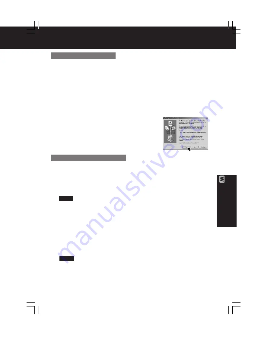
• When the Palmcorder and PC (with Windows 2000) are connected via USB, a
message, such as the one below, is displayed.
The following message is displayed. However, testing by the manufacturer
has confirmed functionality of this palmcorder with Windows XP/2000.
Click [Yes] and proceed.
4
Go to step 5 below.
For Windows 2000 users
3
Connect the Palmcorder to your PC (Windows) using the USB Cable (supplied).
• “CONNECT WITH PC” and “WEB CAM” are displayed in the EVF and LCD monitor.
A gray box is also displayed. The image within the box can be used with
communication.
• Place the Palmcorder so that you are in the picture.
• To confirm if the connection between the Palmcorder and PC is correct, please refer
to “Audio Tuning Wizard” on page 85.
• When connecting for the first time using Windows 98SE or Me, the OS installation
CD may be required.
4
Go to step 5 below.
5
Connect the A/V Cable (supplied) to the Audio Adaptor (supplied).
• For PCs with no built-in mic, connecting the A/V Cable (supplied) to the Audio
Adaptor (supplied), the Palmcorder replaces the mic.
• If the speaker and mic are in close proximity, howling may occur.
• Do not disconnect the USB Cable while in use.
This could be a source of trouble. For more details, please read the corresponding
Help file.
• Close the application, then disconnect the USB Cable.
For Windows 98SE/Me users
Note
Note
DV202_402PN.p 81-83.p65
02/02/13, 17:54
83
Содержание PV-DV102PN
Страница 11: ...11 ...
Страница 12: ...12 ...
Страница 13: ...13 ...
Страница 18: ...4 P C B Holder Fig 8 1 Fig 8 2 4 1 11 2 REMOVAL OF CSP IC Fig 8 3 18 ...
Страница 19: ...4 1 11 3 INSTALLATION OF CSP IC Fig 8 4 19 ...
Страница 20: ...Fig 8 5 20 ...
Страница 21: ...4 1 11 4 CSP IC LOCATION Fig 8 6 21 ...
Страница 27: ...5 2 1 Inner Parts Location 5 2 1 1 TOP VIEW Fig DM1 1 27 ...
Страница 28: ...5 2 1 2 BOTTOM VIEW Fig DM1 2 28 ...
Страница 30: ...5 2 3 Mechanism Base Unit Fig DM3 30 ...
Страница 31: ...5 2 4 Guide Piece L Guide Piece R Garage Unit Fig DM4 31 ...
Страница 32: ...5 2 5 Cylinder Unit Fig DM5 32 ...
Страница 33: ...5 2 6 Dumper Unit Fig DM6 33 ...
Страница 34: ...5 2 7 DEW Sensor DEW Cable Fig DM7 34 ...
Страница 35: ...5 2 8 Mechanism F P C Unit Fig DM8 35 ...
Страница 36: ...5 2 9 Reduction Gear B Fig DM9 36 ...
Страница 37: ...5 2 10 Mechanism Cover Unit Fig DM10 37 ...
Страница 38: ...5 2 11 Idler Arm Unit Center Gear Fig DM11 38 ...
Страница 39: ...5 2 12 Tension Arm Unit Fig DM12 39 ...
Страница 40: ...5 2 13 S Reel Table T Reel Table Fig DM13 40 ...
Страница 41: ...5 2 14 T Break Unit Fig DM15 41 ...
Страница 42: ...5 2 15 Pinch Arm Unit Fig DM16 42 ...
Страница 43: ...5 2 16 Rail Fig DM17 43 ...
Страница 44: ...5 2 17 Cylinder Base Unit Fig DM18 44 ...
Страница 45: ...5 2 18 S T Arm Unit S T Post Unit Fig DM19 45 ...
Страница 46: ...5 2 19 Loading Motor Unit Fig DM20 46 ...
Страница 47: ...5 2 20 Sensor F P C Fig DM21 47 ...
Страница 48: ...5 2 21 Tension Drive Arm S Brake Drive Lever Fig DM22 48 ...
Страница 49: ...5 2 22 Cam Gear Fig DM23 49 ...
Страница 50: ...5 2 23 Pinch Drive Arm Intermediate Gear Fig DM24 50 ...
Страница 51: ...5 2 24 Mode Switch Fig DM25 51 ...
Страница 52: ...5 2 25 MIC Switch Fig DM26 52 ...
Страница 53: ...5 2 26 Main Plate Unit Fig DM27 53 ...
Страница 54: ...5 2 27 T4 Drive Arm Fig DM28 54 ...
Страница 55: ...5 2 28 Drive Pulley Fig DM29 55 ...
Страница 56: ...5 2 29 Capstan Unit Timing Belt Capstan Adjust Spring Fig DM30 56 ...
Страница 57: ...5 2 30 Lock Lever Unit Lock Pick Lever Fig DM31 57 ...
Страница 58: ...6 ADJUSTMENT PROCEDURES 6 1 SERVICE FIXTURES TOOLS 58 ...
Страница 59: ...59 ...
Страница 72: ...10 2 FRONT CASE SECTION 72 ...
Страница 73: ...10 3 CCD AND LENS SECTION 73 ...
Страница 74: ...10 4 TOP CASE AND EVF SECTION 74 ...
Страница 75: ...10 5 SIDE CASE R AND LCD SECTION Model PV DV102 PV DV202 75 ...
Страница 76: ... Model PV DV402 76 ...
Страница 77: ...10 6 MECHANISM SECTION 77 ...
Страница 78: ...10 7 PACKING PARTS AND ACCESSORIES SECTION 78 ...
Страница 89: ...285 LSGB0031 MULTIMEDIA CARD BADGE 1 89 ...
Страница 165: ......


