background image

69

PC 

Connection

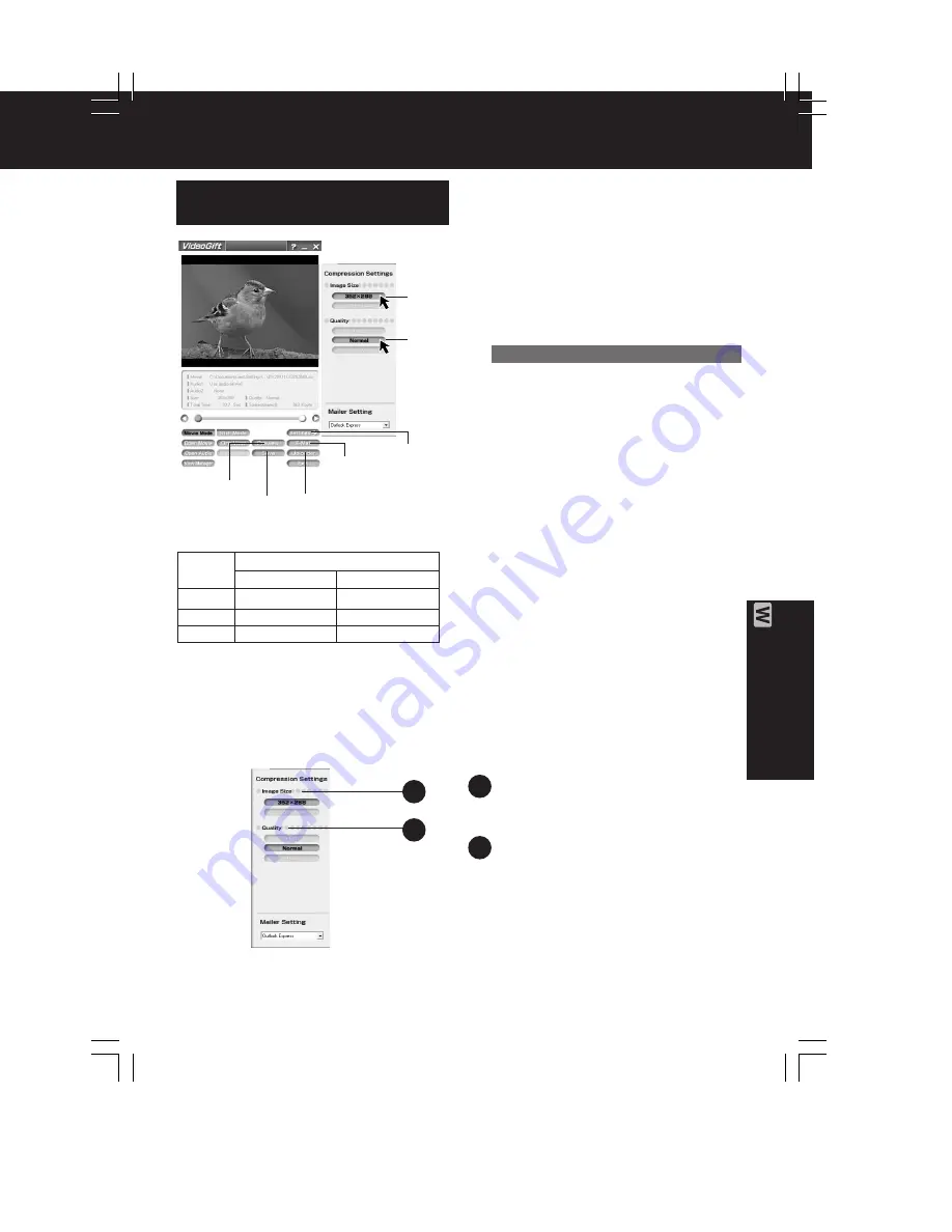
Image Size
You can select the image size
(352 x 288 or 176 x 144).

Quality
You can select the image quality
(High, Normal, Low).

1

2

Setting the Size and Quality
of Motion and Still Image

4

Settings

1

Repeat steps 1~4 on page 61 to
run the PHOTOVU/MPEG4 Movie
Messenger  System.

2

Click [VideoGift] to display the
VideoGift  screen.
• The image captured last is displayed

in the VideoGift screen.

• If “Unable To Locate DLL” warning

indication is displayed, please see
page 90.

3

Select a Motion or Still image.
(See steps 4~or 

4

~

6

 on page 65.)

• The selected Motion or Still image is

displayed on the VideoGift screen.

4

Press [Settings] to display the
“Compression Settings” screen.

5

Set the Image Size and Quality.
• See “Size of Compressed File” to the

left.

6

Click [Save] to save the compressed
image to your PC.
Click [Preview] to view the
compressed Motion Image.
Click [E-mail] to send the e-mail
message.
Click [Uploader] to upload to the
PictureStage Home Page.

6

Preview

6

E-Mail

Image

Quality

High

Normal

Low

Image Size

352 x 288 pixels 176 x 144 pixels

Size of Compressed File

3000 KB/min
2000 KB/min
1000 KB/min

3000 KB/min
2000 KB/min
1000 KB/min

1000 KB/min

600 KB/min
360 KB/min

1

2

5

5

PHOTOVU/MPEG4  Movie  Messenger  System

Caution for Windows 2000 users

6

Save

6

Uploader

DV202_402PN.p 68-72.p65

02/02/13, 17:54

69

Содержание PV-DV102PN

Страница 1: ... VMD0202020C3 Digital Video Camcorder PV DV102PN PV DV202PN PV DV402PN SPECIFICATIONS 2002 Matsushita Electric Industrial Co Ltd All rights reserved Unauthorized copying and distribution is a violation of law 1 ...

Страница 2: ... test 2 After removing an electrical assembly equipped with ES devices place the assembly on a conductive surface such as aluminum foil to prevent electrostatic charge buildup or exposure of the assembly 3 Use only a grounded tip soldering iron to solder or unsolder ES devices 4 Use only an antistatic solder removal device Some solder removal devices not classified as antistatic ESD protected can ...

Страница 3: ...ire or other hazards Do not modify the original design without permission of manufacturer 2 An Isolation Transformer should always be used during the servicing of AC Adaptor whose chassis is not isolated from the AC power line Use a transformer of adequate power rating as this protects the technician from accidents resulting in personal injury from electrical shocks It will also protect AC Adaptor...

Страница 4: ... in parallel with a 0 15 F capacitor between each exposed metallic part on the set and a good earth ground as shown in Figure 1 3 Use an AC voltmeter with 1 k V or more sensitivity to measure the potential across the resistor 4 Check each exposed metallic part and measure the voltage at each point 5 Reverse the AC plug in the AC outlet and repeat each of the above measurements 6 The potential at a...

Страница 5: ...viceability They are not necessarily used Note 1 The LCD open close SW is for changing between LCD Display or EVF Display When turning on LCD Display place some paper or tape etc on LCD open close SW so that this SW stays ON 2 Connect the F P C s to the connectors verifying the direction of F P C as shown 3 Use a grounded ESD wrist strap while disassembling the Lens portion 4 Use extreme care when...

Страница 6: ...4 1 2 SIMPLIFIED FAULT FINDING DATA SELF DIAGNOSTIC SYSTEM When following conditions occur the Power LED will flash according to the condition Fig 2 1 6 ...

Страница 7: ... any of the following numbers appear on screen the palmcorder may need service Do not remove the battery if attached and write down the displayed number Fig 2 2 Note While battery remains the Error No will be displayed again when 7 ...

Страница 8: ... 1 The Non ZIF connectors and the ZIF connectors are used on the unit And there are 2 types Type A Type B of Non ZIF connectors 2 To remove the F P C from the Non ZIF connector use the Plier for Non ZIF Connector LSVQ0028 to pull out the F P C as shown The same Plier for Non ZIF Connector LSVQ0028 should also be used to install the F P C to the Non ZIF Connector Fig 3 1 3 Connect the F P C s to th...

Страница 9: ...als Loading DC to Portion a DC to Portion b Unloading DC to Portion a DC to Portion b Fig 4 4 1 5 METHOD FOR EJECTING WITH POWER OFF CAUTION Make sure that a cassette tape is not in when this method is used or a cassette tape will be damaged When a cassette tape is jammed DO NOT eject manually Refer to HOW TO REMOVE A JAMMED TAPE 1 Insert the Pin or Straightened Paper Clip into the hole on the Cas...

Страница 10: ...k Lever of Mechanism Chassis Ass y 3 The Cassette Cover will open Eject Fig 5 4 1 6 SIGNAL DESCRIPTION ON INTERFACE BOARD FOR ELECTRICAL ADJUSTMENT LSUP0007 A signal check can be performed using the Interface Board 10 ...

Страница 11: ...11 ...

Страница 12: ...12 ...

Страница 13: ...13 ...

Страница 14: ...LY ASSEMBLY PROCEDURES 2 Apply 3 V DC Power Supply to the Portion a and b on the Mechanism F P C Unit Note DO NOT let eject the Garage Unit with grasping the Cassette Cover If the Garage Unit is in the up position a cassette tape may be damaged Fig 6 1 3 When the Mechanism is in EJECT position snapped sound remove the Power Supply immediately 4 Rewind the tape into a cassette tape by turning the C...

Страница 15: ...All EEPROM data in Main menu and then press Enter key 3 Select 5 Save all EEPROM data in Read Save Write All EEPROM data menu and then press Enter key 4 Input the file name and then press the Enter key The data of EEPROM IC will be stored to your PC 2 How to write the EEPROM data which was stored in your PC to EEPROM IC 1 Start up the PC EVR Adjustment Program 2 Select 3 Read Save Write All EEPROM...

Страница 16: ...ite the data of EEPROM IC after replacing Main C B A as follows Selecting 6 Writing from stored data files ID Number with stored data file will be written automatically Selecting 7 Writing of initial data ID Number needs to be input There are two methods a or b to input ID Number as follows a When writing ID Number from the saved data 1 Select 3 Read Save Write All EEPROM data in Main menu and the...

Страница 17: ...4 1 10 HOW TO REPLACE THE LAMP LSLL0028 OF BUILT IN LIGHT Fig 7 4 1 11 REPLACEMENT PROCEDURES FOR CSP CHIP SIZE PACKAGE IC 4 1 11 1 EQUIPMENT 1 Pre Heater 2 Spot Heater 3 Vacuum Pick up 17 ...

Страница 18: ...4 P C B Holder Fig 8 1 Fig 8 2 4 1 11 2 REMOVAL OF CSP IC Fig 8 3 18 ...

Страница 19: ...4 1 11 3 INSTALLATION OF CSP IC Fig 8 4 19 ...

Страница 20: ...Fig 8 5 20 ...

Страница 21: ...4 1 11 4 CSP IC LOCATION Fig 8 6 21 ...

Страница 22: ...section of this service manual 4 1 13 REPLACEMENT PROCEDURE FOR LEADLESS CHIP COMPONENT The following procedures are recommended for the replacement of the leadless components used in this Unit 1 Preparation for replacement A Soldering Iron Use a pencil type soldering iron using less than 30 watts B Solder Eutectic Solder Tin 63 Lead 37 is recommended C Soldering time Do not apply heat for more th...

Страница 23: ...e leadless component with a twisting motion Note A Do not attempt to lift the component off the board until the component is completely disconnected from the board by a twisting action The leadless component is attached to the PCB with glue So carefully twist the component when removing it so as not to break or damage any fail under the component B Take care not to break the copper foil on the pri...

Страница 24: ... running change basis however IC6001 M32121MCA123 is supplied only as a replacement part When replacing IC6001 as in the following cases it is necessary to replace the resistor at the same time or IC6001 may have a short life When replacing IC6001 M32121FCAWG with IC6001 M32121MCA123 be sure to move resistor Ref No R6051 to the R6050 loacation Fig 10 1 Fig 10 2 24 ...

Страница 25: ...5 DISASSEMBLY ASSEMBLY PROCEDURES 5 1 CABINET SECTION 5 1 1 DISASSEMBLY FLOWCHART This flow chart indicates the disassembly steps of the cabinet parts and the P C Boards in order to gain access to item s to be serviced When reassembling perform the step s in the reverse order Bend route and dress the wires as they were originally Fig D1 25 ...

Страница 26: ...or some other soft material under the P C Boards or Unit to prevent damage 3 When reinstalling ensure that the connectors are connected and electrical components have not been damaged 4 Do not supply power to the unit during disassembly and reassembly 5 1 2 Disassembly Method 5 2 MECHANISM SECTION 26 ...

Страница 27: ...5 2 1 Inner Parts Location 5 2 1 1 TOP VIEW Fig DM1 1 27 ...

Страница 28: ...5 2 1 2 BOTTOM VIEW Fig DM1 2 28 ...

Страница 29: ...5 2 2 STOP Position Confirmation Check the following points to confirm that the Mechanism is in STOP Position from the top side Fig DM2 29 ...

Страница 30: ...5 2 3 Mechanism Base Unit Fig DM3 30 ...

Страница 31: ...5 2 4 Guide Piece L Guide Piece R Garage Unit Fig DM4 31 ...

Страница 32: ...5 2 5 Cylinder Unit Fig DM5 32 ...

Страница 33: ...5 2 6 Dumper Unit Fig DM6 33 ...

Страница 34: ...5 2 7 DEW Sensor DEW Cable Fig DM7 34 ...

Страница 35: ...5 2 8 Mechanism F P C Unit Fig DM8 35 ...

Страница 36: ...5 2 9 Reduction Gear B Fig DM9 36 ...

Страница 37: ...5 2 10 Mechanism Cover Unit Fig DM10 37 ...

Страница 38: ...5 2 11 Idler Arm Unit Center Gear Fig DM11 38 ...

Страница 39: ...5 2 12 Tension Arm Unit Fig DM12 39 ...

Страница 40: ...5 2 13 S Reel Table T Reel Table Fig DM13 40 ...

Страница 41: ...5 2 14 T Break Unit Fig DM15 41 ...

Страница 42: ...5 2 15 Pinch Arm Unit Fig DM16 42 ...

Страница 43: ...5 2 16 Rail Fig DM17 43 ...

Страница 44: ...5 2 17 Cylinder Base Unit Fig DM18 44 ...

Страница 45: ...5 2 18 S T Arm Unit S T Post Unit Fig DM19 45 ...

Страница 46: ...5 2 19 Loading Motor Unit Fig DM20 46 ...

Страница 47: ...5 2 20 Sensor F P C Fig DM21 47 ...

Страница 48: ...5 2 21 Tension Drive Arm S Brake Drive Lever Fig DM22 48 ...

Страница 49: ...5 2 22 Cam Gear Fig DM23 49 ...

Страница 50: ...5 2 23 Pinch Drive Arm Intermediate Gear Fig DM24 50 ...

Страница 51: ...5 2 24 Mode Switch Fig DM25 51 ...

Страница 52: ...5 2 25 MIC Switch Fig DM26 52 ...

Страница 53: ...5 2 26 Main Plate Unit Fig DM27 53 ...

Страница 54: ...5 2 27 T4 Drive Arm Fig DM28 54 ...

Страница 55: ...5 2 28 Drive Pulley Fig DM29 55 ...

Страница 56: ...5 2 29 Capstan Unit Timing Belt Capstan Adjust Spring Fig DM30 56 ...

Страница 57: ...5 2 30 Lock Lever Unit Lock Pick Lever Fig DM31 57 ...

Страница 58: ...6 ADJUSTMENT PROCEDURES 6 1 SERVICE FIXTURES TOOLS 58 ...

Страница 59: ...59 ...

Страница 60: ... 2 MECHANICAL ADJUSTMENT 6 2 1 Comparison between adjustment items and replacement parts 6 2 2 TENSION POST ADJUSTMENT Purpose To maintain a constant tape tension so that the tape runs with stability 60 ...

Страница 61: ...Post goes to the most left side by applying DC Power Supply 3 V to the Loading Motor terminal 2 Confirm that there is a space of 0 mm 0 5 mm between the right edge of the Tension Post and the left edge of the S3 Post If not with Flat Headed Screwdriver adjust the Tension Adjust Pin so that the space of 0 mm 0 5 mm is made Fig T1 6 2 3 CAPSTAN TILT ADJUSTMENT Purpose To adjust the tilt of the Capst...

Страница 62: ...stment Tool Fig T2 2 6 2 4 T4 POST HEIGHT CONFIRMATION Purpose To confirm so that the height of the T4 Post is proper Symptom If the height of the T4 Post is incorrect the tape might be damaged 1 To remove the Cassette Cover refer to Disassembly Method of CABINET SECTION in DISASSEMBLY ASSEMBLY PROSEDURES 2 After removing the Cassette Cover insert the tape without the Cassette Cover 62 ...

Страница 63: ...ting Cable 2 Connect the oscilloscope to Envelope TP on the Interface Board 3 Playback the Tape Path Alignment Tape LSVQ0041 4 Adjust the S1 post by turning the top of post with Post Height Adjustment Fixture LSVQ0021 so that the left half of envelope signal becomes flat as possible 5 Adjust the T1 post by turning the top of post with Post Height Adjustment Fixture LSVQ0021 so that the right half ...

Страница 64: ...DJUSTMENT 6 3 1 INITIAL GUIDELINE The table below shows which adjustments are necessary according to the unit parts and individual parts to be replaced Make sure to perform these adjustments shown below as necessary 64 ...

Страница 65: ...obes 10 1 1 1 2 Frequency Counter 3 Vectorscope 4 Plastic Tip Driver 5 Personal Computer PC IBM PC AT or compatible OS MS DOS or MS Windows CPU 486 or higher Drive 3 5 inch 1 44 MB floppy disk drive Port D Sub 9 pin Serial or D Sub 25 pin Serial Monitor VGA Color 6 PC EVR Adjustment Program VF2D2002DV10 Note 65 ...

Страница 66: ...TFGS2 12 White Chart VFK1164TFWC2 13 Color Bar Chart VFK1164TFCB2 14 Light Box and AC Adaptor for VHS C 15 Infinity Lens with Focus Chart VFK1164TCM02 16 AC Adaptor for DVC 17 43 mm Ring VFK1164TAR43 18 Color Conversion Filter C14 VFK1164TFCT2 6 3 3 PREPARATION 1 Insert a flat headed Screwdriver or similar object into the hole remove the EVR Cover Fig E1 1 2 Connect the Camera Connecting Cable to ...

Страница 67: ...oard to RS232C of the PC with Inter Link Cable 6 Set the SW115 M103 EXMOD1 on the Interface Board to GND 7 Set the SW110 RS232C SEL on the Interface Board to DSUB 8 Set the SW114 M103 VPP on the Interface Board to 3V 9 Set the SW103 RECI on the Interface Board to OFF 10 Set the SW108 BST TEST on the Interface Board to OFF 11 Set the SW109 IRIS on the Interface Board to center 12 Set the SW111 5V S...

Страница 68: ...M 1 Turn on the Personal Computer MS Windows will be set up automatically 2 Restart it in MS DOS mode 3 Change the current directory to the one including the PC EVR Adjustment Program and start up the PC EVR Adjustment Program as follows A If MS DOS is Japanese mode input us and then press ENTER key to be US mode on Fig E2 1 68 ...

Страница 69: ...Menu will be displayed 4 Select the model number which you are servicing and then press Enter key The starting display will be displayed 5 Perform set up items according to menu until Main Menu is displayed 6 3 5 HOW TO USE MAIN MENU 6 3 5 1 Main Menu Select a Sub Menu to check adjust the unit by pressing UP DOWN Key in Main Menu Then press ENTER Key The Sub Menu will be displayed Note Menu 6 thro...

Страница 70: ... 1 SCHEMATIC DIAGRAM CIRCUIT BOARD LAYOUT NOTES 7 2 MAIN SCHEMATIC DIAGRAMS 7 3 REAR SCHEMATIC DIAGRAM 7 4 MICROPHONE FRONT EVF BACKLIGHT SCHEMATIC DIAGRAMS 7 5 LCD SCHEMATIC DIAGRAM MODELS PV DV102 PV DV202 7 6 LCD SCHEMATIC DIAGRAM MODEL PV DV402 7 7 INTERCONNECTION SCHEMATIC DIAGRAM 7 8 VOLTAGE CHART 8 CIRCUIT BOARD LAYOUT 8 1 MAIN C B A 8 2 REAR C B A 70 ...

Страница 71: ...8 3 MICROPHONE FRONT EVF BACKLIGHT C B A 8 4 LCD C B A MODELS PV DV102 PV DV202 8 5 LCD C B A MODEL PV DV402 9 BLOCK DIAGRAMS 10 EXPLODED VIEWS 10 1 MAIN PARTS SECTION 71 ...

Страница 72: ...10 2 FRONT CASE SECTION 72 ...

Страница 73: ...10 3 CCD AND LENS SECTION 73 ...

Страница 74: ...10 4 TOP CASE AND EVF SECTION 74 ...

Страница 75: ...10 5 SIDE CASE R AND LCD SECTION Model PV DV102 PV DV202 75 ...

Страница 76: ... Model PV DV402 76 ...

Страница 77: ...10 6 MECHANISM SECTION 77 ...

Страница 78: ...10 7 PACKING PARTS AND ACCESSORIES SECTION 78 ...

Страница 79: ...11 REPLACEMENT PARTS LISTS BEFORE REPLACING PARTS READ THE FOLLOWING 11 1 REPLACEMENT NOTES 11 1 1 General Notes 1 Use only original replacement parts 79 ...

Страница 80: ...replacement parts according to the parts list 5 Parts different in shape or size may be used However only interchangeable parts will be supplied as service replacement parts 6 Parts with mark VED in the Remarks column are supplied from VED Others are supplied from MKE 7 Item numbers with capital letter E Example E10 E20 in the Ref No column are shown in the exploded views 8 Parts whose Ref Nos are...

Страница 81: ...parts In case any parts indicated by NOTE require replacing be sure to replace the whole unit e g entire Front Case Unit 11 1 2 Mechanical Replacement Notes 1 Section No of parts shown in Exploded Views are indicated in the Remarks column 2 Abbreviation RTL Retention Time Limited This indicates that the retention time is limited for this item After 81 ...

Страница 82: ... products be sure to replace both the DEW Sensor and the DEW Cables Refer to DEW Sensor DEW Cable of MECHANISM SECTION in DISASSEMBLY ASSEMBLY PROCEDURES 6 Mechanism Chassis Ass y Ref No 1 replacement note When replacing the Mechanism Chassis Ass y be sure to perform the Envelope Output Adjustment Refer to ENVELOPE OUTPUT ADJUSTMENT in MECHANICAL ADJUSTMENT 7 Front Case Unit Ref No 301 replacement...

Страница 83: ...e Remarks column are CSP Chip Size Package IC 6 IC6007 replacement note When replacing this IC be sure to write the initial data with PC EVR Adjustment Program 7 IC6001 replacement note Two types of IC6001 M32121FCAWG or M32121MCA123 are used on a running change basis however IC6001 M32121MCA123 is supplied only as a replacement part When replacing IC6001 as in the following cases it is necessary ...

Страница 84: ...02 L403 and L502 on Main C B A have been changed on a running change basis When servicing these parts be sure to confirm whether the product is an early one or a later one by checking the part number suffix on Main C B A as shown below In early products LSJB8165 without suffix In later products LSJB8165 1 etc with suffix 84 ...

Страница 85: ...part number of the replacement parts are different for early products and later products as shown When servicing these parts be sure to replace with the proper parts Please note that D1101 has been deleted in later products 11 2 MECHANICAL REPLACEMENT PARTS LIST 85 ...

Страница 86: ...HOLDER 4 NOTE 50 LSYK0853 ELECTRONIC VIEWFINDER UNIT 4 NOTE 51 LSSC0546 EVF ESD ANGLE 4 NOTE 52 LSGT0063 EYE SIGHT LEVER B 4 NOTE 53 LSMB0270 EYE SIGHT LEVER A 4 NOTE 54 L5BDAXG00005 LIQUID CRYSTAL DISPLAY PANEL 4 NOTE 55 LSKD0328 LENS HOLDER 4 NOTE 56 LSFL0134 LENS 4 NOTE 57 LSDL0212 LED DIFFUSION SHEET PLASTIC 4 NOTE 58 LSDL0210 PROTECT PLATE A PLASTIC 4 NOTE 59 LSMD0323 EVF PROTECT B 4 NOTE 60 ...

Страница 87: ...7 109 K2CB2CB00014 AC CORD W PLUG 7 110 PV DAC11 D AC ADAPTOR UNIT 7 110 PV DAC11 A AC ADAPTOR UNIT 7 112 LSJA0280 AUDIO VIDEO CABLE W PLUG 7 113 LSSQ0293 INFRARED REMOTE CONTROL UNIT 7 115 K1HA05CD0001 UNIVERSAL SERIAL BUS CABLE W PLUG 7 118 RP SD008BMK0 SD MEMORY CARD B C 7 118 RP SD008MMK0 SD MEMORY CARD B C 7 119 LSFT0491 APPRICATION SOFTWARE CD ROM A 7 119 LSFT0492 APPRICATION SOFTWARE CD ROM...

Страница 88: ...VMFW0045 SHEET NYLON RAYON 6 241 LSXD0017 CYLINDER BASE UNIT 6 242 LSXD0021 S POST UNIT 6 242 VXDS0210 S POST UNIT 6 243 VXLS1118 S ARM UNIT 6 244 LSXD0020 T POST UNIT 6 244 VXDS0209 T POST UNIT 6 245 VXLS1119 T ARM UNIT 6 261 LSKM0806 FRONT COVER A B 5 261 LSKM0769 FRONT COVER C 5 NOTE 262 LSYK0882 LCD EARTH PLEATE UNIT C 5 263 EDTCA34QA0 LIQUID CRYSTAL DISPLAY PANEL C 5 264 LSXY0354 LCD REFRECT ...

Страница 89: ...285 LSGB0031 MULTIMEDIA CARD BADGE 1 89 ...

Страница 90: ... VMX2750 CUT WASHER STEEL 6 477 VMX2028 CUT WASHER STEEL 6 478 XQN14 B12FN SCREW STEEL 6 503 LSHD0073 SCREW STEEL 6 504 XQN2 B35 SCREW STEEL 6 507 XQN14 BJ4 SCREW STEEL 3 509 XQN2 BF8FN SCREW STEEL 5 510 XQN2 BF5FXK SCREW STEEL 1 511 XQN2 BF3FN SCREW STEEL A B 5 701 LSEK0446 ELECTORIC CONDENSER MICROPHONE UNIT A B 4 NOTE 701 LSEK0447 ELECTORIC CONDENSER MICROPHONE UNIT C 4 NOTE 703 LSMG0111 MICROP...

Страница 91: ...ION CABLE 28P LSUA0030 EXTENSION CABLE 11P LSUA0020 EXTENSION CABLE 20P LSVQ0020 CAPSTAN TILT ADJUSTMENT TOOL LSUQ0002 GREASE VFKS0081 GREASE VFK1164LBX1 LIGHT BOX VED VFK1164TCM02 INFINITY LENS WITH FOCUS CHART VED VFK1164TAR43 43mm RING VED VFK1164TFCT2 COLOR CONVERSION FILTER C14 VED LSVQ0021 POST HEIGHT ADJUSTMENT FIXTURE LSUP0016 CAMERA CONNECTING CABLE LSUP0007 INTERFACE BOARD FOR ELECTRICAL...

Страница 92: ...52A2 IC LOGIC E S D IC302 MN31121SA E1 IC LOGIC E S D IC401 MN103001GEA1 IC 32BIT MICROCONTROLLER E S D IC402 PDIUSBD12 IC LOGIC E S D IC501 AD9843AJST IC LINEAR IC502 XC62FP2902MR IC CMOS STANDARD LOGIC E S D IC701 LB1837MLTEL3 IC LINEAR IC701 LB1837M TE L IC LINEAR IC701 LB1837MTEL3 IC LINEAR IC702 LB1837MLTEL3 IC LINEAR IC702 LB1837M TE L IC LINEAR IC702 LB1837MTEL3 IC LINEAR IC703 C0ABCZ000008...

Страница 93: ...TRANSISTOR SI PNP CHIP Q704 B1ADCF000063 TRANSISTOR SI PNP CHIP Q705 2SD1819A0L TRANSISTOR SI NPN CHIP Q705 B1ABCF000020 TRANSISTOR SI NPN CHIP Q706 2SD2216J08 TRANSISTOR SI NPN CHIP Q706 B1ABCF000104 TRANSISTOR SI NPN CHIP Q707 2SD1819A0L TRANSISTOR SI NPN CHIP Q707 B1ABCF000020 TRANSISTOR SI NPN CHIP Q708 2SD2216J08 TRANSISTOR SI NPN CHIP Q708 B1ABCF000104 TRANSISTOR SI NPN CHIP Q901 2SD2216J08 ...

Страница 94: ...Q1101 B1BDEB000001 TRANSISTOR SI PNP CHIP Q1102 2SD1819A0L TRANSISTOR SI NPN CHIP Q1102 B1ABCF000020 TRANSISTOR SI NPN CHIP Q1103 2SB1462J08 TRANSISTOR SI PNP CHIP Q1103 B1ADCF000072 TRANSISTOR SI PNP CHIP Q1104 2SD2216J08 TRANSISTOR SI NPN CHIP Q1104 B1ABCF000104 TRANSISTOR SI NPN CHIP Q1105 2SB1462J08 TRANSISTOR SI PNP CHIP Q1105 B1ADCF000072 TRANSISTOR SI PNP CHIP Q1106 2SB1462J08 TRANSISTOR SI...

Страница 95: ...D1101 RD12S T1B DIODE ZENER CHIP 12V See Replacement Note D1102 MA2J111008 DIODE SI CHIP D1102 B0ACCK000005 DIODE SI CHIP D1102 MA2J11100L DIODE SI CHIP D3001 MA2S111008 DIODE SI CHIP D3001 B0ACCK000003 DIODE SI CHIP D3001 MA2S11100L DIODE SI CHIP D6001 B0JCDD000002 DIODE SI CHIP D6002 MA2S728008 DIODE SI CHIP D6002 B0JCDD000002 DIODE SI CHIP D6002 MA2S72800L DIODE SI CHIP D6003 MA2S728008 DIODE S...

Страница 96: ...W 470 R414 ERJ2GEJ472X MGF CHIP 1 16W 4 7K R415 ERJ2GEJ102X MGF CHIP 1 16W 1K R418 ERJ2GEJ682X MGF CHIP 1 16W 6 8K R420 ERJ2GEJ103X MGF CHIP 1 16W 10K R421 ERJ2GEJ471X MGF CHIP 1 16W 470 R422 ERJ2GEJ473X MGF CHIP 1 16W 47K R423 ERJ2GEJ103X MGF CHIP 1 16W 10K R424 ERJ2GEJ473X MGF CHIP 1 16W 47K R425 ERJ2GEJ103X MGF CHIP 1 16W 10K R426 ERJ2GE0R00X MGF CHIP 1 16W 0 R430 ERJ8GEYF180V MGF CHIP 1 16W 18...

Страница 97: ...GF CHIP 1 16W 120K R732 ERJ2GEJ822X MGF CHIP 1 16W 8 2K R733 ERJ2GEJ184X MGF CHIP 1 16W 180K R735 ERJ2GEJ562X MGF CHIP 1 16W 5 6K R736 ERJ2GEJ102X MGF CHIP 1 16W 1K R737 ERJ2GEJ224X MGF CHIP 1 16W 220K R738 ERJ2GEJ394X MGF CHIP 1 16W 390K R739 ERJ2GEJ823X MGF CHIP 1 16W 82K R741 ERJ2GEJ473X MGF CHIP 1 16W 47K R742 ERJ2GEJ273X MGF CHIP 1 16W 27K R743 ERJ2GEJ474X MGF CHIP 1 16W 470K R744 ERJ2GEJ102X...

Страница 98: ... ERJ2GEJ273X MGF CHIP 1 16W 27K R1009 ERJ2GEJ473X MGF CHIP 1 16W 47K R1010 ERJ2GEJ154X MGF CHIP 1 16W 150K R1011 ERJ2GEJ124X MGF CHIP 1 16W 120K R1012 ERJ2GEJ102X MGF CHIP 1 16W 1K R1013 ERJ2GEJ472X MGF CHIP 1 16W 4 7K R1014 ERJ2GEJ472X MGF CHIP 1 16W 4 7K R1015 ERJ2GEJ102X MGF CHIP 1 16W 1K R1016 ERJ2GEJ102X MGF CHIP 1 16W 1K R1017 ERJ2GEJ102X MGF CHIP 1 16W 1K R1018 ERJ2GEJ151X MGF CHIP 1 16W 15...

Страница 99: ...16W 15K R1073 ERJ2GEJ222X MGF CHIP 1 16W 2 2K R1074 ERJ2GEJ221X MGF CHIP 1 16W 220 R1075 ERJ2GEJ560X MGF CHIP 1 16W 56 R1078 ERJ2GEJ221X MGF CHIP 1 16W 220 R1079 ERJ2GEJ222X MGF CHIP 1 16W 2 2K R1080 ERJ2GEJ103X MGF CHIP 1 16W 10K R1081 ERJ2GEJ222X MGF CHIP 1 16W 2 2K R1082 ERJ2GEJ222X MGF CHIP 1 16W 2 2K R1085 ERJ2GEJ222X MGF CHIP 1 16W 2 2K R1086 ERJ2GEJ473X MGF CHIP 1 16W 47K R1087 ERJ2GEJ473X ...

Страница 100: ... 8W 0 R3001 ERJ2GEJ103X MGF CHIP 1 16W 10K R3005 ERJ2GEJ153X MGF CHIP 1 16W 15K R3006 ERJ2GEJ682X MGF CHIP 1 16W 6 8K R3010 ERJ2GEJ153X MGF CHIP 1 16W 15K R3011 ERJ2GEJ103X MGF CHIP 1 16W 10K R3015 ERJ2GEJ153X MGF CHIP 1 16W 15K R3016 ERJ2GEJ103X MGF CHIP 1 16W 10K R3019 ERJ2GEJ153X MGF CHIP 1 16W 15K R3020 ERJ2GEJ103X MGF CHIP 1 16W 10K R3024 ERJ2GE0R00X MGF CHIP 1 16W 0 R3025 ERJ2GEJ105X MGF CHI...

Страница 101: ...1 16W 22 R3264 ERJ2GEJ220X MGF CHIP 1 16W 22 R3265 ERJ2GEJ220X MGF CHIP 1 16W 22 R3266 ERJ2GEJ220X MGF CHIP 1 16W 22 R3502 ERJ2GE0R00X MGF CHIP 1 16W 0 R3902 ERJ2GEJ104X MGF CHIP 1 16W 100K R3903 ERJ2GEJ104X MGF CHIP 1 16W 100K R4305 ERJ2GEJ100X MGF CHIP 1 16W 10 R4501 ERJ2GEJ472X MGF CHIP 1 16W 4 7K R4503 ERJ2GEJ100X MGF CHIP 1 16W 10 R4504 ERJ2GEJ100X MGF CHIP 1 16W 10 R4505 ERJ2GEJ681X MGF CHIP...

Страница 102: ...R6033 ERJ2GEJ473X MGF CHIP 1 16W 47K R6034 ERJ2GEJ473X MGF CHIP 1 16W 47K R6035 ERJ2GEJ473X MGF CHIP 1 16W 47K R6036 ERJ2GEJ473X MGF CHIP 1 16W 47K R6037 ERJ3GEYJ563V MGF CHIP 1 16W 56K R6038 ERJ3GEYJ563V MGF CHIP 1 16W 56K R6039 ERJ2GEJ102X MGF CHIP 1 16W 1K R6040 ERJ2GEJ102X MGF CHIP 1 16W 1K R6041 ERJ3GEYJ563V MGF CHIP 1 16W 56K R6042 ERJ3GEYJ563V MGF CHIP 1 16W 56K R6043 ERJ2GEJ102X MGF CHIP 1...

Страница 103: ... 1 8W 22 R6089 ERJ2GEJ102X MGF CHIP 1 16W 1K R6090 ERJ2GEJ102X MGF CHIP 1 16W 1K R6091 ERJ2GEJ473X MGF CHIP 1 16W 47K R6092 ERJ2GEJ473X MGF CHIP 1 16W 47K R6093 ERJ2GEJ473X MGF CHIP 1 16W 47K R6094 ERJ2GEJ473X MGF CHIP 1 16W 47K R6095 ERJ2GEJ473X MGF CHIP 1 16W 47K R6096 ERJ2GEJ103X MGF CHIP 1 16W 10K R6097 ERJ2GEJ473X MGF CHIP 1 16W 47K R6098 ERJ2GEJ394X MGF CHIP 1 16W 390K R6099 ERJ2GEJ102X MGF ...

Страница 104: ... MGF CHIP 1 16W 680 R6145 ERJ2GEJ103X MGF CHIP 1 16W 10K R6146 ERJ2GEJ102X MGF CHIP 1 16W 1K R6147 ERJ2GEJ102X MGF CHIP 1 16W 1K R6148 ERJ2GEJ102X MGF CHIP 1 16W 1K R6149 ERJ2GEJ104X MGF CHIP 1 16W 100K R6150 ERJ2GEJ103X MGF CHIP 1 16W 10K R6151 ERJ2GEJ332X MGF CHIP 1 16W 3 3K R6152 ERJ2GEJ332X MGF CHIP 1 16W 3 3K R6153 ERJ2GEJ332X MGF CHIP 1 16W 3 3K R6154 ERJ2GEJ105X MGF CHIP 1 16W 1M R6155 ERJ2...

Страница 105: ...10V 1UF C507 ECJ1VF1A105Z C CHIP 10V 1UF C508 ECUE1C104ZFV C CHIP 16V 0 1UF C509 ECJ0EF1C104Z C CHIP 16V 0 1UF C510 ECJ0EF1C104Z C CHIP 16V 0 1UF C511 ECJ0EF1C104Z C CHIP 16V 0 1UF C512 ECJ1VF1A105Z C CHIP 10V 1UF C701 ECJ2YF1A475Z C CHIP 10V 4 7UF C702 ECJ2YF1A475Z C CHIP 10V 4 7UF C703 ECEV1CA100S ELECTROLYTIC CHIP 16V 10UF C704 ECJ2YF1A475Z C CHIP 10V 4 7UF C706 ECJ2YF1A475Z C CHIP 10V 4 7UF C7...

Страница 106: ...C CHIP 50V 47PF C1027 ECJ0EC1H470J C CHIP 50V 47PF C1028 ECJ0EC1H470J C CHIP 50V 47PF C1029 ECJ2VF1C105Z C CHIP 16V 1UF C1030 ECEV1CA220S ELECTROLYTIC CHIP 16V 22UF C1032 F1L1C106A011 C CHIP 16V 10UF C1034 F1J0J4750004 C CHIP 6 3V 0 47UF C1036 F1J0J4750004 C CHIP 6 3V 0 47UF C1038 F1J0J4750004 C CHIP 6 3V 0 47UF C1039 F1J1C1050011 C CHIP 16V 1UF C1040 VCUSQBH105ZF C CHIP 50V 1UF C1041 F1J1C1050011...

Страница 107: ...ECJ2VC1H471J C CHIP 50V 470PF C2010 ECJ1VB1E183K C CHIP 25V 0 018UF C2012 ECJ2VB1E104K C CHIP 25V 0 1UF C2013 ECJ1VF1C104Z C CHIP 16V 0 1UF C2014 ECJ1VF1C104Z C CHIP 16V 0 1UF C2016 ECJ2YB1A105K C CHIP 10V 1UF C2017 ECJ0EB1C103K C CHIP 16V 0 01UF C2018 ECJ2YB1A105K C CHIP 10V 1UF C2021 ECJ0EF1C104Z C CHIP 16V 0 1UF C2022 ECJ0EF1C104Z C CHIP 16V 0 1UF C2024 ECJ0EF1C104Z C CHIP 16V 0 1UF C2027 ECJ0E...

Страница 108: ... Replacement Note C3112 ECJ2YB1A105K C CHIP 10V 1UF C3114 ECJ0EF1C104Z C CHIP 16V 0 1UF C3115 VCUSQAV105ZF C CHIP 35V 1UF See Replacement Note C3115 ECJ2VF1C105Z C CHIP 16V 1UF See Replacement Note C3116 ECEV0GA101S ELECTROLYTIC CHIP 4V 100UF B C C3117 ECJ2YB0J225K C CHIP 6 3V 2 2UF B C C3118 ECJ2YB0J225K C CHIP 6 3V 2 2UF C3119 ECEV0GA101S ELECTROLYTIC CHIP 4V 100UF C3120 ECJ0EB1C103K C CHIP 16V ...

Страница 109: ...K C CHIP 10V 1UF C5001 ECST0JY106 TANTALUM CHIP 6 3V 10UF C5002 ECST0JY226R TANTALUM CHIP 6 3V 22UF C5004 ECJ0EB1H681K C CHIP 50V 680PF C5005 ECJ0EB1C103K C CHIP 16V 0 01UF C5007 ECJ0EB1C103K C CHIP 16V 0 01UF C5009 ECJ0EF1C104Z C CHIP 16V 0 1UF C5011 ECJ0EB1C103K C CHIP 16V 0 01UF C5012 ECJ0EF1C104Z C CHIP 16V 0 1UF C5013 ECJ0EC1H120J C CHIP 50V 12PF C5014 ECJ0EC1H120J C CHIP 50V 12PF C5015 ECJ0E...

Страница 110: ...eplacement Note L403 J0JBC0000025 FERRITE BEAD CHIP See Replacement Note L502 G1C100M00010 COIL CHIP 10UH See Replacement Note L502 J0JBC0000025 FERRITE BEAD CHIP See Replacement Note L701 ERJ6GEY0R00V MGF CHIP 1 10W 0 L901 LSLJFHB100NF COIL CHIP 10UH L1001 G1C100MA0065 CHOKE COIL 10UH L1002 G1C100MA0065 CHOKE COIL 10UH L1003 G1C220MA0065 CHOKE COIL 22UH L1004 G1C220MA0065 CHOKE COIL 22UH L1005 G1...

Страница 111: ...INDUCTOR 100UH L5002 G1C100K00020 COIL CHIP 10UH L6003 ERJ6GEY0R00V MGF CHIP 1 10W 0 CRYSTAL OSCILLATOR Ref No Part No Part Name Description Remarks X301 LSSX0077 CRYSTAL OSCILLATOR X3001 H0A245500003 CRYSTAL OSCILLATOR X6002 LSSX0071 CRYSTAL OSCILLATOR X6003 LSSX0023 CRYSTAL OSCILLATOR PIN HEADERS Ref No Part No Part Name Description Remarks B1 K1KB40B00019 BOARD TO BOARD 40P B2 K1KA20A00233 BOAR...

Страница 112: ...ion Remarks R6706 ERJ3GEY0R00V MGF CHIP 1 16W 0 R6707 ERJ3GEY0R00V MGF CHIP 1 16W 0 R7001 ERJ3GEYJ331V MGF CHIP 1 16W 330 B C R7003 ERJ3GEYJ561V MGF CHIP 1 16W 560 CAPACITORS Ref No Part No Part Name Description Remarks C1201 ECJ1VF1H103Z C CHIP 50V 0 01UF C1202 ECJ1VF1H103Z C CHIP 50V 0 01UF COILS Ref No Part No Part Name Description Remarks L1201 J0JGC0000034 FERRITE BEAD CHIP L1202 J0JGC0000034...

Страница 113: ... CHIP 32V 1A IP1202 K5H102Z00004 FUSE CHIP 32V 1A IP1202 K5H1022A0003 FUSE CHIP 32V 1A IP1202 K5H102Z00006 FUSE CHIP 32V 1A SWITCHES Ref No Part No Part Name Description Remarks SW1201 ESE22MH4 SWITCH PUSH JACKS Ref No Part No Part Name Description Remarks JK6701 K2HZ105E0001 USB MINI JACK SOCKET JK7001 LSYK0828 BATTERY COVER UNIT A JK7001 LSYK0829 BATTERY COVER UNIT B C JK7003 K1FB104B0026 DV JAC...

Страница 114: ...16W 100K NOTE R4804 ERJ3GEYJ363V MGF CHIP 1 16W 36K NOTE R4805 ERJ3GEYJ822V MGF CHIP 1 16W 8 2K NOTE R4806 ERJ3GEYJ104V MGF CHIP 1 16W 100K NOTE R4807 ERJ3GEYJ363V MGF CHIP 1 16W 36K NOTE R4808 ERJ3GEYJ822V MGF CHIP 1 16W 8 2K NOTE R4809 ERJ3GEYJ471V MGF CHIP 1 16W 470 NOTE R4810 ERJ3GEYJ103V MGF CHIP 1 16W 10K NOTE R4811 D0HB154ZA002 MGF CHIP 1 16W 150K NOTE R4812 D0HB563ZA002 MGF CHIP 1 16W 56K ...

Страница 115: ...VB1H821K C CHIP 50V 820PF NOTE C4815 ECJ1VB1E223K C CHIP 25V 0 022UF NOTE C4816 ECJ1VB1E223K C CHIP 25V 0 022UF NOTE C4817 F1J1A1050002 C CHIP 10V 1UF NOTE C4818 F1J1A1050002 C CHIP 10V 1UF NOTE C4819 ECJ1VB1H222K C CHIP 50V 0 0022UF NOTE C4820 ECJ1VB1H222K C CHIP 50V 0 0022UF NOTE C4821 ECUE1C104ZFV C CHIP 16V 0 1UF C NOTE COILS Ref No Part No Part Name Description Remarks L4801 J0JBC0000036 FERR...

Страница 116: ...t Name Description Remarks P6501 K1KA03A00304 CONNECTOR 3P NOTE FPC CONNECTOR Ref No Part No Part Name Description Remarks FP6501 K1MN10A00030 CONNECTOR 10P NOTE MISCELLANEOUS Ref No Part No Part Name Description Remarks U6501 B3RAD0000039 INFRARED RECEOVER NOTE 11 3 5 EVF BACK LIGHT C B A TRANSISTORS Ref No Part No Part Name Description Remarks Q951 2SD2216J0L TRANSISTOR SI NPN CHIP NOTE Q951 2SC...

Страница 117: ...F CHIP 1 16W 0 NOTE CAPACITORS Ref No Part No Part Name Description Remarks C952 ECJ1VF1C104Z C CHIP 16V 0 1UF NOTE C953 ECJ1VF1C104Z C CHIP 16V 0 1UF NOTE C954 ECJ1VF1C104Z C CHIP 16V 0 1UF NOTE C955 ECJ1VF1C104Z C CHIP 16V 0 1UF NOTE FPC CONNECTOR Ref No Part No Part Name Description Remarks FP951 K1MN19B00052 CONNECTOR 19P NOTE FP952 K1MN20B00084 CONNECTOR 20P NOTE 11 3 6 LIQUID CRYSTAL DISPLAY...

Страница 118: ...HIP Q8008 B1ADCF000072 TRANSISTOR SI PNP CHIP Q8009 2SD1819A0L TRANSISTOR SI NPN CHIP Q8009 B1ABCF000020 TRANSISTOR SI NPN CHIP Q8010 UNR511400L TRANSISTOR SI PNP CHIP Q8010 B1GDCFJN0011 TRANSISTOR SI PNP CHIP Q8011 UNR521200L TRANSISTOR SI NPN CHIP Q8011 B1GBCFLL0012 TRANSISTOR SI NPN CHIP Q8012 XP0450100L TRANSISTOR COMPLX CMP SI NPN CHIP Q8014 XP0440100L TRANSISTOR COMPLX CMP SI NPN CHIP Q8104 ...

Страница 119: ... 8K R8025 ERJ3GEYJ153V MGF CHIP 1 16W 15K R8027 ERJ3GEY0R00V MGF CHIP 1 16W 0 R8028 ERJ3GEY0R00V MGF CHIP 1 16W 0 R8029 ERJ3GEY0R00V MGF CHIP 1 16W 0 R8031 ERJ3GEY0R00V MGF CHIP 1 16W 0 R8032 ERJ3GEY0R00V MGF CHIP 1 16W 0 R8034 ERJ3GEYJ101V MGF CHIP 1 16W 100 R8035 ERJ3GEYJ101V MGF CHIP 1 16W 100 R8036 ERJ3GEYJ101V MGF CHIP 1 16W 100 R8037 ERJ3GEYJ102V MGF CHIP 1 16W 1K R8038 ERJ3GEYJ393V MGF CHIP...

Страница 120: ...0 1UF C8107 ECUV1A106KBP C CHIP 10V 10UF C8108 ECHU1H273JB5 POLYESTER CHIP 50V 0 027UF C8109 LSCUCAD150J C CHIP 2KV 15PF C8110 LSCUCAD150J C CHIP 2KV 15PF C8113 ECJ1VB1C104K C CHIP 16V 0 1UF C8114 ECUV0J105KBV C CHIP 6 3V 1UF C8115 ECST0JY106 TANTALUM CHIP 6 3V 10UF C8116 ECJ1VF1C104Z C CHIP 16V 0 1UF C8117 F1J1C1050011 C CHIP 16V 1UF C8118 ECJ1VF1C104Z C CHIP 16V 0 1UF COILS Ref No Part No Part N...

Страница 121: ...5 2SD1819A0L TRANSISTOR SI NPN CHIP Q8005 B1ABCF000020 TRANSISTOR SI NPN CHIP Q8006 2SD1819A0L TRANSISTOR SI NPN CHIP Q8006 B1ABCF000020 TRANSISTOR SI NPN CHIP Q8007 UNR521200L TRANSISTOR SI NPN CHIP Q8007 B1GBCFLL0012 TRANSISTOR SI NPN CHIP Q8008 2SB1462J08 TRANSISTOR SI PNP CHIP Q8008 B1ADCF000072 TRANSISTOR SI PNP CHIP Q8009 2SD1819A0L TRANSISTOR SI NPN CHIP Q8009 B1ABCF000020 TRANSISTOR SI NPN...

Страница 122: ...EYJ102V MGF CHIP 1 16W 1K R8014 ERJ3GEYJ223V MGF CHIP 1 16W 22K R8016 ERJ3GEYJ472V MGF CHIP 1 16W 4 7K R8017 ERJ3GEYJ223V MGF CHIP 1 16W 22K R8019 ERJ3GEYJ222V MGF CHIP 1 16W 2 2K R8021 ERJ3GEYJ102V MGF CHIP 1 16W 1K R8022 ERJ3GEYJ562V MGF CHIP 1 16W 5 6K R8023 ERJ3GEY0R00V MGF CHIP 1 16W 0 R8024 ERJ3GEYJ682V MGF CHIP 1 16W 6 8K R8025 ERJ3GEYJ153V MGF CHIP 1 16W 15K R8027 ERJ3GEY0R00V MGF CHIP 1 1...

Страница 123: ...ECJ2YB0J225K C CHIP 6 3V 2 2UF C8015 ECJ2YF1C225Z C CHIP 16V 2 2UF C8016 F1K1C2250005 C CHIP 16V 2 2UF C8017 ECJ2YF1C225Z C CHIP 16V 2 2UF C8019 ECJ1VB1C104K C CHIP 16V 0 1UF C8107 ECUV1A106KBP C CHIP 10V 10UF C8108 ECHU1H333JB5 C CHIP 50V 0 033UF C8109 LSCUCAD150J C CHIP 2KV 15PF C8110 LSCUCAD150J C CHIP 2KV 15PF C8113 ECJ1VB1C104K C CHIP 16V 0 1UF C8114 ECUV0J105KBV C CHIP 6 3V 1UF C8115 ECST0JY...

Страница 124: ...No Part Name Description Remarks T8101 ETJ11K94AM TRANSFORMER MISCELLANEOUS Ref No Part No Part Name Description Remarks 721 VMZW0660 INSULATION SHEET PLASTIC 11 3 8 ELECTRICAL PARTS LOCATED ON CHASSIS Ref No Part No Part Name Description Remarks 735 LSEP8172A1 SD HOLDER UNIT NR 12 SCHEMATIC DIAGRAMS FOR PRINTING WITH LETTER SIZE 124 ...

Страница 125: ...5 47 10 11 41 40 35 9 OB CLAMP PULSE DUMMY CLAMP PULSE PRE BLANKING PULSE MUX VGA DOUBLE SAMPLING HOLD 10BIT A D CONVERTER D A CONVERTER REC VIDEO CAMERA SIGNAL 23 19 21 22 46 47 48 20 16 12 3 4 FCK TG CS L TG SERIAL DATA TG SERIAL CLOCK 6MHz CLOCK 18MHz CLOCK A D CLOCK 1 VD HD CLAMP CLAMP CAMERA DATA 0 9 CAMERA DAC SERIAL CLOCK CAMERA DAC SERIAL DATA CAMERA DAC CS L FCK 18MHz CAM HD CAM VD 8 2FCK...

Страница 126: ...B CS L USB INTERFACE 6MHz OSC READ CONTROL SD SERIAL DATA 1 SD SERIAL CLOCK SD WRITE PROTECT L SD IN L SD SERIAL DATA 0 WRITE CONTROL TXD RXD USB CS L USB DATA 0 7 RGB ENCODER SW SW 148 141 H SYNC 220 V SYNC H SYNC V SYNC 219 LCD POL LCD POLARITY 206 40 39 52 15 16 11 26 25 192 193 194 66 65 67 56 49 47 41 38 31 26 21 16 12 9 161 162 B1 11 B1 10 B1201 10 B1201 11 70 71 58 48 68 FP6 4 FP6 5 FP6 9 S...

Страница 127: ...B1 14 B1 15 B1 27 B1 26 B1201 14 B1201 15 B1201 27 B1201 26 1 5 2 3 4 TPB RESET L XWEH XWEL XWEL XRE XRE ADDRESS STROBE ADDRESS STROBE 27MHz CLOCK 27MHz CLOCK 24 576MHz CLOCK TPB TPA TPA GND 50 51 53 56 58 61 63 66 68 69 41 10 45 27 8 5 3 AMP A D CONVERTER AMP A D CONVERTER REC C CONTROL REC CLOCK EQ HOLD REC CONTROL HEAD SW PULSE 2 HEAD SW PULSE 1 PB H REC ON OFF CONTROL D A CONVERTER EQUALIZER A...

Страница 128: ...A 13 5MHz CLOCK FROM IC6001 233 WIDE CONTROL FROM IC6001 221 Y GAIN CONTROL FROM IC6001 222 C GAIN CONTROL TO FROM SYSTEM CONTROL BLOCK DAGRAM FROM SYSTEM CONTROL BLOCK DAGRAM TO FROM VIDEO SIGNAL PROCESS I BLOCK DAGRAM Y C VIDEO 5V 35 39 38 31 COMP Q3001 Q3002 Q3005 WITH A V SELECT WITH S JACK NOT USED WITH S JACK Q3004 Q3003 36 37 SYNC SEPA 35 65 81 67 IC3503 SW 3 7 1 7 1 2 DEC ACC 111 112 115 1...

Страница 129: ...IGNAL PROCESS B1 23 B1201 23 B1 20 B1 21 B1201 20 B1201 21 24 17 20 26 1 56 19 18 9 10 EVR MUTE MUTE EVR 6 7 62 60 59 64 TO FROM SYSTEM CONTROL BLOCK DIAGRAM 19 FROM IC3001 97 AUDIO MASTER CLOCK 28 FROM IC6001 71 RESET L RESET L FROM IC6001 85 AUDIO I F CS FROM IC6001 112 AUDIO I F SERIAL CLOCK TO IC6001 114 AUDIO I F SERIAL DATA 1 FROM IC6001 115 AUDIO I F SERIAL DATA 0 FROM IC3001 48 HEADPHONE O...

Страница 130: ... DRIVE MAGICVU LED ON L 184 UNREG CAMERA OPERATIONKEY SW JOG POWER MENU REC PAUSE PHOTOSHOT POWER CAM DSC OFF VTR OFF ON MODE SELECT SW POS 3 POS 2 POS 1 PIN NO OF IC6001 MODE EJECT STOP1 CASS DOWN STOP2 LOADING PLAY FF REW REV CUE 9 8 7 L L L H H L H L H L H H 33 WITH MAGICVU WITH DSC WITH DSC IC6008 TIMER IC6003 SYS UNREG X6002 32 kHz OSC TIMER CS X IN X OUT VDD TIMER SERIAL CLOCK TIMER SERIAL D...

Страница 131: ...96 210 97 75 236 CAP TORQUE LIMIT CAP SPEED ERROR CYL SPEED ERROR CYL FG CYL FG CYL PG CAP FG CAP DIRECTION CTL 237 CYL ON CTL CYL VM CYL SW CAP SW CAP FG CAP VM SP MODE LP MODE TRIANGLE WAVE TO FROM POWER SUPPLY BLOCK DIAGRAM 18 18 18 18 18 18 FP4 2 FP3 2 3 5 14 19 16 21 18 49 CYL DRIVE CLOCK 47 48 34 33 24 TO INTERFACE BOARD FOR EVR ADJUSTMENT CYLINDER MOTOR DRIVE POSITION DETECTOR LOGIC HALL MA...

Страница 132: ...TA V REF H ZOOM ENCODER FOCUS ENCODER FP701 11 FP701 10 FP701 12 FP701 9 ZOOM ENCODER FOCUS ENCODER 5V 3V LED DRIVE 202 203 181 LED CONTROL Q6009 FP701 15 FP701 16 FP701 17 FP701 18 10 13 8 11 5 4 7 2 6 1 LOGIC CONTROL MOTOR DRIVE 6V REGULATOR IC702 FOCUS MOTOR DRIVE 22 24 25 19 27 29 26 FOCUS MOTOR DRIVE CONTROL 0 FOCUS MOTOR DRIVE CONTROL 1 FOCUS MOTOR DRIVE CONTROL 2 FOCUS MOTOR DRIVE 0 FOCUS M...

Страница 133: ...PANEL UNIT Q8002 Q8001 Q8006 Q8005 Q8004 Q8003 Q8008 Q8007 12V 5V 3V 2 43 29 7 5V VCC 3V 42 VCC 3V 10 VCC 12V VCC 3V FRP FP7 1 FP7 2 REVERSE NORMAL OPEN CLOSE TO FROM SYSTEM CONTROL BLOCK DIAGRAM TO FROM VIDEO SIGNAL PROCESS I BLOCK DIAGRAM FROM SYSTEM CONTROL BLOCK DIAGRAM TO INTERFACE BOARD FOR EVR ADJUSTMENT TO IC6001 98 LCD REVERSE L TO IC6001 99 LCD OPEN L FROM IC6001 173 LCD ON H V SYNC LCD ...

Страница 134: ... 3V FRP FP7 1 FP7 2 REVERSE NORMAL OPEN CLOSE TO FROM SYSTEM CONTROL BLOCK DIAGRAM TO FROM VIDEO SIGNAL PROCESS I BLOCK DIAGRAM FROM SYSTEM CONTROL BLOCK DIAGRAM TO INTERFACE BOARD FOR EVR ADJUSTMENT TO IC6001 98 LCD REVERSE L TO IC6001 99 LCD OPEN L FROM IC6001 173 LCD ON H V SYNC LCD R LCD POL LCD G LCD B LCD CS LCD SERIAL CLOCK LCD SERIAL DATA LCD R LCD G LCD B LCD V COM FROM IC6001 172 LCD BAC...

Страница 135: ...ERATOR VOLTAGE REGULATOR BLACK LEVEL GAIN ADJUSTMENT 5 26 21 22 18 19 20 17 25 24 23 16 15 13 FP8 22 FP8 17 FP8 21 FP8 16 FP8 20 FP8 19 FP8 18 FP951 11 FP951 12 FP951 13 FP951 9 FP951 10 FP951 14 FP951 15 FP951 5 FP951 6 FP951 7 FP951 8 FP951 16 FP951 17 FP951 19 FP951 4 FP951 18 FP951 3 FP952 10 FP952 18 FP952 9 FP952 8 FP952 12 FP952 11 FP952 7 FP952 6 FP952 16 FP952 15 FP952 14 FP952 13 FP952 5...

Страница 136: ...T DETECT Q1105 Q1101 Q1102 D1102 Q1106 LATCH Q1104 FP1 6 7 FP1 8 9 FP6501 6 7 FP6501 8 9 P6501 1 P6501 3 LIGHT SOCKET UNIT FROM IC6001 32 LIGHT ON H L1012 Q1021 SHUNT REGULATOR CAM 3 2V EVF LCD 3V Q1023 D1005 IC1003 UNREG TO IC6001 253 BATTERY T TO IC6001 252 BATTERY D SYS UNREG L1008 L1011 L1007 L1009 L1010 LCD BL 5V REG 5V A HA 5V LCD 5V AF 5V Q1018 Q1019 L1016 L1013 L1014 L1015 REG 2 5V A EVF B...

Страница 137: ...305 C4302 C4301 C412 C411 C401 C3901 C3560 C3559 C3558 C3557 C3556 C3555 C3554 C3553 C3552 C3551 C3522 C3521 C3520 C3519 C3518 C3515 C3514 C3513 C3512 C3511 C3510 C3509 C3507 C3505 C3260 C3254 C3252 C3251 C3221 C3220 C3219 C3218 C3217 C3216 C3215 C3214 C3213 C3212 C3211 C3210 C3209 C3208 C3207 C3206 C3205 C3204 C3203 C3202 C3201 C3121 C312 C3119 C3117 C3116 C3104 C310 C309 C308 C305 C3040 C304 C30...

Страница 138: ...1 8 14 1 1 10 11 20 7 8 14 1 7 C6040 C6039 C6038 C6037 C6035 C6034 C6033 C6032 C6031 C6030 C6029 C6028 C6025 C6023 C6021 C6017 C6014 C6013 C407 C406 C6010 C410 C6006 C4501 C1004 C4504 C4503 C4506 C4510 C4508 C4502 C4507 C4516 C4513 C4522 C6005 C3103 C3115 C2002 C1078 C3110 C3107 C4515 C4514 C4512 C4511 C4509 C4523 C5002 C5001 C4524 C1066 C6003 C1054 C6007 C6011 C404 C2001 C402 C1088 C3502 C3501 L3...

Страница 139: ...BY THE SIGN HAVE SPECIAL CHARACTERISTICS IMPORTANT FOR SAFETY WHEN REPLACING ANY OF THESE COMPONENTS USE ONLY THE SPECIFIED PARTS COMPONENT SIDE FOIL SIDE REAR C B A LSEP8183A1 LSEP8183B1 PV DV102 PV DV202 PV DV402 NOTE CIRCUIT BOARD LAYOUT SHOWS COMPONENTS INSTALLED FOR VARIOUS MODELS FOR PROPER PARTS CONTENT FOR THE MODEL YOU ARE SERVICING PLEASE REFER TO THE SCHEMATIC DIAGRAM AND PARTS LIST NOT...

Страница 140: ...6501 1 3 1 2 9 10 D6502 U6501 MAGICVU INFRARED RECEIVER UNIT LSJB8167 E C B R958 FP952 LSJB8169 R952 R951 C951 R954 R953 R955 Q951 D951 BACKLIGHT 1 20 COMPONENT SIDE FOIL SIDE EVF BACK LIGHT C B A LSEP8169A1 FP951 C954 C953 R957 R956 C952 C955 1 19 LSJB8169 MICROPHONE C B A LSXM0023 LSXM0024 FRONT C B A LSEP8167B1 LSEP8167C1 EVF BACK LIGHT C B A LSEP8169A1 PV DV102 PV DV202 PV DV402 NOTE CIRCUIT B...

Страница 141: ...12 R8011 R8010 R8009 R8008 R8007 R8006 R8005 R8004 R8003 R8002 R8001 R8046 R8044 R8045 R8105 R8047 R8104 R8108 R8106 R8107 R8111 R8109 R8110 R8022 R8021 L8104 Q8012 D8001 C8113 R8113 C8002 C8003 C8004 C8008 C8013 C8016 C8018 C8019 C8119 C8006 C8114 C8116 C8118 C8107 C8005 C8010 Q8015 C8007 C8115 L8001 L8002 L8005 L8004 L8003 C8108 IC8001 T8101 FP8003 C8109 C8014 C8017 C8012 C8011 FP8002 C8009 Q801...

Страница 142: ... R8047 R8046 R8037 R8036 R8035 R8034 R8013 R8012 R8011 R8006 R8005 C8004 C8003 C8002 C8005 R8004 R8109 R8111 R8110 C8114 Q8106 Q8107 C8112 C8107 D8101 R8104 Q8105 Q8104 C8108 R8040 R8029 R8028 R8027 R8010 R8009 R8008 L8103 L8104 IC8001 C8110 C8109 T8101 FP8002 7 8 6 5 VH GND 3 4 1 2 1 25 1 24 1 48 12 13 24 25 35 34 HV GND 1 1 1 1 LSJB8178 E C B E C B E C B E C B E C B E C B E C B E C B E C B E C B...

Страница 143: ...6 L 1 1 Cassette Cover Ass y MAIN PARTS PORTION 8 Mechanism Chassis Ass y 5 Rear C B A 7 Top Case EVF Ass y Side Case R Ass y How to read chart shown above A Order of Procedure steps When reassembling perform steps s in reverse order B Ref No C Part to be removed or installed D Section No E Identification of part to be removed unhooked unlocked released unplugged unclamped or unsoldered 3404 404 3...

Страница 144: ... Ass y be sure to perform the Envelope Output Adjustment Refer to ENVELOPE OUTPUT ADJUSTMENT in MECHANICALADJUSTMENT NOTE 4 In early products a sheet is used When replacing the Side Case L Unit it is not neccessary to place the sheet WARNING COMPARISON CHART OF MODELS MARKS MODEL MARK PV DV102 PV DV202 PV DV402 A B C C C Note 1 Parts with no Ref No in EXPLODED VIEW are not supplied And some Ref No...

Страница 145: ...ved unhooked unlocked released unplugged unclamped or unsoldered 3 404 404 3 Screws 2 L 1 2 Looking Tabs L 1 F Refer to Notes in chart 2 2 2 2 2 2 2 STEP No Ref No PART REMOVE NOTE 4 9 Lamp 1 2 3 Light Protector Light Reflector Lamp Socket Unit A B C D E F 3 L 3 281 282 284 283 Section No How to read chart shown above A Order of Procedure steps When reassembling perform steps s in reverse order B ...

Страница 146: ...urn hazard IMPORTANT SAFTY NOTICE COMPONENTS IDENTIFIED BY THE SIGN HAVE SPECIAL CHARACTERISTICS IMPORTANT FOR SAFETY WHEN REPLACING ANY OF THESE COMPONENTS USE ONLY THE SPECIFIED PARTS L 2 L 2 Projection L 1 P6501 Note 1 Parts with no Ref No in EXPLODED VIEW are not supplied And some Ref No will be skipped Be sure to make your orders of replacement parts according to the parts list 2 The parts in...

Страница 147: ...ed unplugged unclamped or unsoldered 3 404 404 3 Screws 2 L 1 2 Looking Tabs L 1 F Refer to Notes in chart 3 3 3 10 Optical Filter 3 22 3 STEP No Ref No PART REMOVE NOTE 2 11 Zoom Motor Unit 1 Focus Motor Unit 68 69 A B C D E F Section No How to read chart shown above A Order of Procedure steps When reassembling perform steps s in reverse order B Ref No C Part to be removed or installed D Section ...

Страница 148: ...lability from Factroy LSUQ0002 Availability Part Number A B Note 1 Parts with no Ref No in EXPLODED VIEW are not supplied And some Ref No will be skipped Be sure to make your orders of replacement parts according to the parts list 2 The parts indicated by the dotted line are for Ass y only and are not supplied 3 Disregard Ref No suffixes when ordering parts They are used to describe parts in Disas...

Страница 149: ...fer to Notes in chart 4 4 4 STEP No Ref No PART REMOVE NOTE 2 EVF Back Light C B A LED Holder 1 13 Eye Cap EVF Case Ass y A B C D E F 4 5 402 2 L 3 FP952 FP951 2 L 4 2 L 5 40 E50 57 54 60 58 44 LED Diffusion Sheet LCD Panel 4 L 2 EVF Protect A Protect Plate A 3 6 7 9 L 6 56 55 53 59 14 Lens Lens Holder 14 Eye Sight Lever A EVF Protect B 8 52 14 Eye Sight Lever B How to read chart shown above A Ord...

Страница 150: ...287 289 289 Note 1 Parts with no Ref No in EXPLODED VIEW are not supplied And some Ref No will be skipped Be sure to make your orders of replacement parts according to the parts list 2 The parts indicated by the dotted line are for Ass y only and are not supplied 3 Disregard Ref No suffixes when ordering parts They are used to describe parts in Disassembly Assembly Procedures section not supplied ...

Страница 151: ... 1 2 Looking Tabs L 1 F Refer to Notes in chart How to read chart shown above A Order of Procedure steps When reassembling perform steps s in reverse order B Ref No C Part to be removed or installed D Section No E Identification of part to be removed unhooked unlocked released unplugged unclamped or unsoldered 3404 404 3 Screws 2 L 1 2 Looking Tabs L 1 F Refer to Notes in chart 5 Section No 5 5 5 ...

Страница 152: ...ot supplied And some Ref No will be skipped Be sure to make your orders of replacement parts according to the parts list 2 The parts indicated by the dotted line are for Ass y only and are not supplied 3 Disregard Ref No suffixes when ordering parts They are used to describe parts in Disassembly Assembly Procedures section NOTE 6 In early products a sheet is used When servicing it is not neccessar...

Страница 153: ...ed 3404 404 3 Screws 2 L 1 2 Looking Tabs L 1 F Refer to Notes in chart How to read chart shown above A Order of Procedure steps When reassembling perform steps s in reverse order B Ref No C Part to be removed or installed D Section No E Identification of part to be removed unhooked unlocked released unplugged unclamped or unsoldered 3404 404 3 Screws 2 L 1 2 Looking Tabs L 1 F Refer to Notes in c...

Страница 154: ...4 14 20 15 76 267 268 Note 1 Parts with no Ref No in EXPLODED VIEW are not supplied And some Ref No will be skipped Be sure to make your orders of replacement parts according to the parts list 2 The parts indicated by the dotted line are for Ass y only and are not supplied 3 Disregard Ref No suffixes when ordering parts They are used to describe parts in Disassembly Assembly Procedures section COM...

Страница 155: ... 2 4 Push the Cassette Cover to release the Locking Tab L 1b Fig D2 3 Cassette Cover EJECT Switch Open Slide 5 Push the both side of the Cassette Cover to release the Locking Tabs L 1c and L 1d from the slots of the Side Case R Fig D2 4 6 Open the Cassette Cover as shown Fig D2 5 7 Pinch and pull the Cassette Cover to release the Locking Tab L 1e while holding the Garage Unit carefully as shown Th...

Страница 156: ...sette Cover on the Mechanism Chassis Ass y CAUTION Do not break the Cassette Cover Fig D2 7 2 Push the both side of the Cassette Cover to set the Locking Tabs L 1c and L 1d to slots of the Side Case R Fig D2 8 L 1f L 1e Garage Unit Pull Do not break Push Push L 1c L 1d Slot of Side Case R Slot of Side Case R Push Push Push Push L 1a L 1b 3 Push down the upper portion of the Cassette Cover to close...

Страница 157: ... it as shown Zoom Switch F P C FP9 Main C B A Fig D4 3 Removal of Speaker 1 Open the Hand Strap and release it from the hole of the Strap Angle front 2 Remove the Screw 404 2 3 Remove the Strap Angle front and the Speaker Angle Then remove the Speaker Hand Strap Speaker Angle hole of Strap Angle front Fig D5 4 Installation of Main C B A Take care not to damage the Flexible Cables 1 Connect the Fle...

Страница 158: ...emoving the CCD C B A take care that the OpticalFilterandInfraredCutFilter Formodelwithout Magic VU does not fall out 2 Take extreme caution when removing the CCD C B A because it is easily damaged by static electricity Use a Wrist Strap while removing and installing 3 Do not touch the CCD window surface when handling Installation of CCD C B A Filter Rubber Optical Filter Infrared Cut Filter For m...

Страница 159: ...n of Lens Holder Eye Sight Lever A Eye Sight Lever B 1 InstalltheEyeSightLeversAandBintotheEVFProtect B taking care that Portion a of the Eye Sight Lever A is installed in the correct direction as shown Then tighten the Screw 402 2 Install the Lens Holder so that the boss of the Lens Holder is set to Portion a of the Eye Sight Lever A EVF Protect B Lens Holder with Lens Boss Portion a of Eye Sight...

Страница 160: ...red correctly as shown below a b c d Protection Sheet Lead Light Panel Unit Lamp Unit Portion b Portion a LCD C B A Terminal of Lamp Unit Solder Fig D14 18 For model with 2 5 inch LCD Monitor Installation of Lamp Unit Lamp Unit LCD Panel Holder LCD Panel Holder LCD Reflect Sheet LCD Reflect Sheet Open Lead Light Panel Lead Light Panel When installing the Lamp Unit confirm that the Lamp Unit is pos...

Страница 161: ...he Lead Light Panel with 2 Locking Tabs L 5 3 Install the LCD Diffusion Sheet on the Lead Light Panel with 2 Locking Tabs L 4 Be careful of the direction of the LCD Diffusion Sheet Lamp LCD Diffusion Sheet Lead Light Panel L 5 L 5 L 4 LCD Panel L 4 LCD Reflect Frame Fig D17 1 4 After installing the LCD Panel the LCD Earth Plate Unit and the LCD C B A solder both side of the terminal of the Lamp no...

Страница 162: ...onnect operate or adjust this product please read these instructions thoroughly LSQT0597A Models No PV DV202 PV DV402 Digital Video Camcorder Operating Instructions Mini PV DV402 shown DV202_402PN p 1 4 p65 02 02 13 17 51 1 ...

Страница 163: ...is equipment does cause interference to radio or television reception which can be determined by turning the equipment off and on use the equipment in another location and or utilize an electrical outlet different from that used by the receiver If necessary consult the dealer or an experienced radio TV technician for help You may find the booklet Something About Interference available from FCC loc...

Страница 164: ... retained for future reference 3 Heed Warnings All warnings on the unit and in the operating instructions should be adhered to 4 Follow Instructions All operating and maintenance instructions should be followed 5 Cleaning Unplug this video unit from the wall outlet before cleaning Do not use liquid or aerosol cleaners Use a dry cloth for cleaning 6 Attachments Do not use attachments not recommende...

Страница 165: ......

Страница 166: ...en Displays OSD 99 MENU OSD 101 Electronic Viewfinder LCD Monitor Indications 105 Index of Controls 109 Index Back Cover Special Features Playback Your Recordings 32 Special Effect Features 34 Digital Features 40 Editing Features 44 Card Features 48 PC Connection TransferringYour Images Windows 55 PHOTOVU MPEG4 Movie Messenger System 59 TransferringYour Images i LINK Windows 73 PHOTOVU MPEG4 Movie...

Страница 167: ...ver Software for Windows 98SE Me 2000 XP and Macintosh USB Device Driver for Windows 98SE Me 2000 XP PHOTOVU MPEG4 Movie Messenger System for Windows 98SE Me 2000 XP Built in SD Drive for Macintosh ArcSoft Software for Windows 95 98SE Me 2000 XP and Macintosh LSFT0492 Microsoft Windows and Windows Media are registered trademarks of Microsoft in the United States and other countries Macintosh iMac ...

Страница 168: ...up window side facing out 4 Press PUSH TO CLOSE to close the Cassette Compartment Cover Note When inserting the cassette make sure it is facing the right direction and then push it in completely EasyCassetteEject Insertion If the Palmcorder is connected to a power source the cassette can be inserted and ejected without turning the Palmcorder on To remove the cassette Slide TAPE EJECT to open the C...

Страница 169: ...om the front clasp and thread the Strap through the loop in the Lens Cap Cord Reattach the Hand Strap Lens Cap Attaching the Shoulder Strap 2 1 3 Attaching the Lens Cap Strap Thread the Lens Cap Strap through the Strap Attachment Ring as shown Hand Strap Hand Strap 1 Undo the two strap ends from their buckles 2 Thread the strap ends through the Strap Attachment Rings 3 Reinsert the strap ends thro...

Страница 170: ... p 34 Pause Select pp 16 17 36 47 Stop Set pp 16 17 32 47 Slow Frame Advance Forward pp 35 36 Slow Frame Advance Backward pp 35 36 Index Search Forward pp 36 37 Index Search Backward pp 36 37 Speaker Volume p 33 1 Hold down LIGHT for more than 0 7 seconds to turn ON or OFF will appear on the screen To brighten the natural colors in a scene Using the Built in Light Caution This light becomes hot du...

Страница 171: ...the desired Palmcorder For VCR 2 Press these buttons at the same time For VCR 1 Press these buttons at the same time Remote Controlling Two Palmcorders Note 1Set POWER to VCR or CAMERA The POWER Lamp lights red Be sure POWER is fully turned to VCR or CAMERA position 2Press MENU to display the VCR or CAMERA mode menu screen 3Rotate JOG KEY to select SET UP in the CAMERA mode menu screen or PLAY MOD...

Страница 172: ...tection Film Note Remove the Protection Film before use Before you begin Charge the Battery p 14 2Set POWER to VCR or CAMERA 1 2 These Palmcorders are equipped with the Easy Cassette Eject System so it is easy to insert or remove tapes even when on a tripod p 7 4 Insert a cassette record tab up window side facing out Make sure the record tab is closed p 7 5 Press PUSH TO CLOSE mark to close the Ca...

Страница 173: ...OPEN to unlock the LCD monitor Swing it fully open and adjust the angle To Watch Playback in the LCD Liquid Crystal Display When the LCD monitor is fully open the Viewfinder automatically turns OFF 2 Press LCD OPEN to unlock the LCD monitor Swing it fully open and adjust the angle 3 Press REW to rewind the tape 4Press PLAY to start playback 5 Press STOP to stop playback Before you begin Charge the...

Страница 174: ...Memory Card optional p 93 Capacity 8 MB 8 MB 16 MB 16 MB 32 MB 64 MB SD Memory Card write protection switch A write protection switch is located on the SD Memory Card Sliding the switch to the LOCK position prevents writing on or formatting the card Write protection Switch To remove the Memory Card Press here to eject the card About the M CARD Lock Switch Note By sliding M CARD Lock to LOCK you ca...

Страница 175: ...he CHARGE Lamp Charge the Battery within an ambient temperature range of 10 C 50 F and 30 C 86 F If charging is done in extreme low or high temperatures Battery charge time increases CHARGE Lamp flashes when The Battery is being charged but charging is taking longer than normal Charging is not possible Remove the Battery once wait a short time then re attach it for charging Note 1 Insert the Batte...

Страница 176: ...sufficiently charged or worn out Battery If charging is done in extreme low or high temperatures Battery charge time increases Safety precautions Do not place the Battery near or dispose of in fire Do not directly connect short circuit the positive and negative terminals Never attempt to disassemble or reas semble the Battery To avoid damage to the Battery Do not drop or jar the Battery Use the Ba...

Страница 177: ...s Press JOG KEY repeatedly to move back to an item and correct A built in Battery maintains clock operation If the Palmcorder is not connected to a power source for a few months the built in battery may discharge and CLOCK BATTERY indication appears p 99 EXAMPLE When DATE TIME setting is completed press MENU three times to start the clock and exit 2002 YEAR Push PUSH Rotate PUSH JAN FEB MONTH MONT...

Страница 178: ...t PROG AE or CINEMA 3 REC MODE CAMERA REC MODE menu is displayed To select REC SPEED AUDIO REC INDEX SHUTTER SELF REC WIND CUT or ZOOM MIC 4 SET UP CAMERA SET UP menu is displayed To select REMOTE BEEP or MAGICVU PV DV402 only 5 DISPLAY SETTING DISPLAY SETTING menu is displayed To select DISPLAY C RESET DATE TIME or CLOCK SET 6 LCD EVF SETTING LCD EVF SETTING menu is displayed To select LCD BRIGHT...

Страница 179: ...e TAPE EJECT EVF To conserve power After 5 minutes the Record Pause mode will automatically change to Standby mode To resume recording set POWER to OFF and then ON again When the Palmcorder is aimed at excessively bright objects or bright lights a vertical bar may appear in the picture This is a normal characteristic of the CCD pick up device Try to avoid this whenever possible SimpleRecording Bef...

Страница 180: ...COLOR below 3 Start recording Using the LCD monitor will reduce battery operating time Close the LCD monitor completely when not in use Using the LCD Monitor 1LCD OPEN Note 180 90 90 Camera Recording To adjust the LCD EVF BRIGHTNESS or COLOR 1 Press MENU to display the main menu screen 2 Rotate JOG KEY to select LCD EVF SETTING from the main menu screen Menu OSD pp 102 104 3 Press JOG KEY to displ...

Страница 181: ...to make an interesting slide show etc p 44 1Set POWER to CAMERA 2Press PHOTOSHOT in Record Pause mode PHOTO will appear in the EVF or the LCD monitor If SHUTTER on the menu screen is set to ON a sound effect similar to the shutter of a film camera will be heard when PHOTOSHOT is pressed When PHOTOSHOT is pressed the playback image takes approx 7 seconds to process After that the Camera mode screen...

Страница 182: ...unction 1 Set POWER to CAMERA 2 Press MENU to display the CAMERA mode menu screen 3 Rotate JOG KEY to select REC MODE then press JOG KEY to display the CAMERA REC MODE menu screen 4 Rotate JOG KEY to select ZOOM MIC in the CAMERA REC MODE menu Menu OSD p 101 5 Press JOG KEY to select ON Press MENU twice to exit Z MIC will appear on the screen The Zoom Microphone Function may not work effectively i...

Страница 183: ...While in RECORD mode press STILL and hold for 2 seconds to capture a still picture The captured still picture will be recorded together with sound 2Press STILL once again to release the still picture The camera will resume recording real time pictures Rotate the LCD monitor 180 degrees so it faces the same direction as the lens to record yourself 1 Set POWER to CAMERA 2 Press MENU to display the C...

Страница 184: ...le with a wide screen TV equipped with an S2 picture terminal Backlight 2 3BACK LIGHT The Indicator will not appear in the EVF or LCD monitor when OFF is selected in the DISPLAY menu Note Use when recording a subject that is darker than the surrounding scene in a shadowed area or when the light source is behind your subject 3 4 JOG KEY 5REC PAUSE 1POWER EVF LCD 2MENU 1 Set POWER to CAMERA 2 Press ...

Страница 185: ...SPORTS mode or PORTRAIT mode together with the MagicPix mode in the Digital function camera menu Program AE 3MENU The Auto Exposure feature can be used to make quality recordings in a variety of scene situations Note 1 Set POWER to CAMERA 2 Hold down AUTO MANUAL for more than 0 7 seconds so that the MNL indication appears in the EVF or the LCD monitor 3 Press MENU to display the menu screen 4 Rota...

Страница 186: ...UE or GREEN Press MENU twice to exit To cancel this feature slide MAGICVU 0LUX to OFF The subject can be up to 3 m 10 feet away Note 4 5JOG KEY 3MENU 1POWER 1 3 AFADE Audio Video Fade In Out 2 BREC PAUSE Fade In Starting the first scene with fade in is very effective 1 In REC PAUSE mode hold down FADE until the picture fades out 2 Press REC PAUSE to start recording 3 Release FADE and the picture w...

Страница 187: ... 4 Press JOG KEY to select PinP Press MENU twice to exit this menu PinP will appear in the EVF or the LCD monitor 5 Aim at the scene you wish to place as PinP then press CAMERA STILL to freeze the image 6 Press CAMERA STILL again to place the frozen image as PinP 7 Press REC PAUSE to record a scene with PinP image Press PHOTOSHOT to record a scene with PinP image in PhotoShot mode Press CAMERA STI...

Страница 188: ...d Digital Function turns off 5 Press REC PAUSE to start recording with Photo Title WIPE or MIX screen is displayed at the beginning of the recording Then the Photo Title setting will be cleared automatically You can use PhotoShot images stored on a Memory Card to record a WIPE or MIX effect on a cassette When Photo Title is set to SET the selected image and Title will appear before each recording ...

Страница 189: ...balance in most lighting conditions When the source illumination is a halogen lamp When shooting outdoors on a sunny day The White Balance setting that was previously set manually For manual White Balance adjustment A Rotate JOG KEY to select B Point the Palmcorder at a white object full screen and hold JOG KEY down until indication stops flashing If indication flashes when the Palmcorder is turne...

Страница 190: ... the EVF or the LCD monitor 4Press and hold POWER ZOOM T side Telephoto until the lens is at maximum zoom in 5Turn M FOCUS DIAL until the picture is in focus It may be necessary to back away from the subject to focus the image properly 6Press POWER ZOOM to W or T as desired The subject will remain in focus over the entire zooming range It may be necessary to back away from the subject to focus the...

Страница 191: ...Rotate JOG KEY to choose one of the following shutter speeds Hold down AUTO MANUAL for more than 0 7 seconds to cancel the setting For proper color reproduction it is recommended that you use this feature outdoors For indoor High Speed Shutter recording additional halogen or tungsten light should be provided Fluorescent light will degrade the picture quality More light is required for the fastest ...

Страница 192: ...s to cancel the setting The value to which dB is attached indicates a gain value If this value is too large the quality of the image deteriorates Depending on ZOOM magnification the iris value may not be displayed correctly If you are using Program AE mode you cannot adjust the iris If the iris is adjusted manually the above modes will be canceled Note 3 4 JOG KEY 1POWER Iris Setting WIND CUT You ...

Страница 193: ...monitor to playback your recording Note PHONE Jack Before you begin Connect the Palmcorder to a power source pp 14 15 Insert a recorded cassette When a tape recorded in LP mode on another digital video camera is played back on this unit the picture may appear mosaic Using the LCD monitor reduces battery operating time You can place the Palmcorder on a table etc for viewing Rotate the LCD Monitor 1...

Страница 194: ... PLAY MODE then press JOG KEY to display the VCR PLAY MODE menu screen 4 Rotate JOG KEY to select B SEARCH in the VCR PLAY MODE menu Menu OSD p 103 5 Press JOG KEY to select ON BLANK will appear on the screen 3 4 5 JOG KEY 1POWER Blank Search You can go directly to a blank portion of tape and start recording exactly where you left off RepeatPlayback Adjusting the Volume 2MENU 1 Rotate VOLUME to ad...

Страница 195: ... an instant or mosaic This is normal during this mode Note Note 1Press PAUSE during playback 2Press PLAY or PAUSE to release To protect the tape and video heads your Palmcorder s operating modes will revert as follows STILL STOP after 3 minutes AHold down FAST FORWARD SEARCH during fast forward BHold down REWIND SEARCH during rewind The picture will appear for as long as the button is held down No...

Страница 196: ...yback 2 Press JOG KEY for about 1 second 3 Rotate JOG KEY to adjust the playback speed Rotate JOG KEY clockwise for forward playback Rotate JOG KEY counterclockwise for reverse playback To return to normal playback Press PLAY Playback will continue at normal speed The Variable Speed Search function offers a choice of six playback speeds 1 5X LP mode 1 3X 1X 2X 5X 10X 20X both in forward and revers...

Страница 197: ...ne Index Search mode the shutter sound effect may not be able to be heard even when SHUTTER is set to ON Photo Index Search may fail to detect a recorded PhotoShot image if the image is 3 seconds or less 1 Press MENU to display the VCR mode menu screen 2 Rotate JOG KEY to select PLAY MODE and press JOG KEY to display the VCR PLAY MODE menu screen 3 Rotate JOG KEY to select INDEX and press JOG KEY ...

Страница 198: ...ponse time from pressing the button and the change in the scene number is quite slow Do not press INDEX SEARCH rapidly and continuously During Reverse Index Search mode playback will not begin when a tape rewinds all the way to the beginning Search for a particular scene by using the electronic index marks placed at the beginning of each recording 1 Press MENU to display the VCR mode menu screen 2...

Страница 199: ... PLAY to start playback Press STOP to stop playback Strobe Speeds Strobe Speeds FAST NORM SLOW 9 screen capture time Every 0 3 seconds Every 0 6 seconds Every 1 0 seconds A Multi Image Playback screen cannot be output from the DV terminal or Digital Still Image terminal A Multi screen will have slightly lower image quality Note In Strobe Multi Mode you can select the rate at which a succession of ...

Страница 200: ...ON and set it to LINE INPUT or S VIDEO Check your TV operating instructions for further information 3Start playback or begin a recording Make sure the Palmcorder and TV are turned off while connecting Please connect the A V Cable securely A V OUT Remote Control Only You can display the various EVF and LCD indications on your TV by pressing DISPLAY ON TV on the remote control Press again to remove ...

Страница 201: ... JOG KEY to select D ZOOM1 or D ZOOM2 D ZOOM1 from 10X to 25X D ZOOM2 from 10X to 700X OFF Turn off D ZOOM Press MENU twice to exit 5 Press REC PAUSE to start recording and press POWER ZOOM to zoom in or zoom out The magnification level is always displayed in the EVF or the LCD monitor when DISPLAY is set to ON Menu OSD pp 102 104 6 Repeat steps 2 4 to select OFF to cancel this feature Other Digit...

Страница 202: ...g of video or still images onto the Mini DV tape in low lighting pp 43 101 MagicPixImages 1 Set POWER to CAMERA 2 Press MENU to display the menu screen 3 Rotate JOG KEY to select D FUNCTION and then press JOG KEY to display the CAMERA FUNCTION menu screen 4 Rotate JOG KEY to select D FUNCTION and then press JOG KEY repeatedly to select MAGICPIX Press MENU twice to exit 5 To cancel the Digital Func...

Страница 203: ...ed in both the Recording and Playback VCR modes CAMERA mode VCR mode Other Digital Functions are turned off automatically when the EIS and Digital Zoom are selected A Set POWER to VCR B Press PLAY to start playback C Press EIS to stabilize the picture D Press EIS again to cancel Be sure that D E I S is turned off when not needed Note When using D E I S in VCR mode the image size is slightly larger...

Страница 204: ...GICPIX Not available during playback Color recording of video or still images onto the Mini DV in low lighting p 41 Only Manual Focus is available WIPE Successive scenes are separated in a way which simulates the drawing of a curtain MIX The current scene is mixed in with the following scene during scene changes PinP PinP Still image is displayed on the Main Picture SEPIA Only available during pla...

Страница 205: ...e and A DUB flashes in the EVF or the LCD monitor Go to step 4 2PLAY 2PAUSE 3A DUB Before you begin Connect the external Microphone if used PV DV402 only Turn on the Palmcorder Insert a pre recorded tape to be dubbed Built in Microphone The AUDIO REC setting in CAMERA MENU mode should be as follows Select 12 bit if you do not want the original sound to be completely replaced during an audio dub If...

Страница 206: ...in the menu for playback the sound will be stereo regardless of the AUDIO OUT setting If you recorded in LP mode you cannot use the A DUB feature Note You can set an automatic Dubbing stop point DRESET AMENU APress MENU to display the VCR menu screen BRotate JOG KEY to select DISPLAY SETTING and then press JOG KEY to display the DISPLAY SETTING menu CRotate JOG KEY to select DISPLAY and then press...

Страница 207: ...e recorded tape into the source playing Palmcorder and a blank tape with record tab in place into the target VCR Recorder 2Press PLAY on the Palmcorder When the tape reaches the point you want to start dubbing press PAUSE 3Place the VCR into REC PAUSE mode See VCR manual 4Simultaneously press PAUSE on both units to begin copying 5Press STOP on both units when copying is completed S Video Cable not...

Страница 208: ...g 6 Press STOP on the recording unit and then press STOP on the playing unit to end dubbing When two Palmcorders are used for dubbing it is recommended that the Remote Control VCR1 or VCR2 setting be used to avoid improper operation When two Palmcorders are connected using the DV Interface cable i LINK not supplied a Video Editing Controller cannot be used Do not connect both an S Video Cable or A...

Страница 209: ...sible damage to the memory Before you begin Connect the Palmcorder to a power source pp 14 15 Set POWER to OFF before inserting a Memory Card p 13 Card PhotoShot Memory Card will not work when DV Interface Cable i LINK is connected Warning Warning M CARD Lock 2MENU The number of images given for each mode applies when all images are taken in same mode You can change recording modes at any time bef...

Страница 210: ...onnected Warning Card Features Cautions for the Memory Card While Memory Card data is being read do not remove it turn off the power or subject unit to vibrations and or shocks Do not leave the Memory Card in a place with high temperature a place exposed to direct sunlight or a place where electromagnetic waves and static electricity can be generated Electromagnetic waves static electricity malfun...

Страница 211: ...ti Image screen or NEXT next image Press M STOP to return to the Multi Playback screen Note If the file number is changed the Palmcorder cannot read the file data This product is compliant with DCF Design rule for Camera File System Images saved on the Memory Card using other Digital Still Cameras that are compliant with DCF can be viewed on this product While PLEASE WAIT is displayed DO NOT turn ...

Страница 212: ...ide the M CARD Lock Switch to unlock then set POWER to M CARD PLAY PUSH PLAY KEY is displayed for 10 seconds 2 Press M PLAY to display the Multi playback screen PLEASE WAIT appears on screen 3 Press M DEL to display the DELETE menu then rotate and press JOG KEY to select PAGE DELETE PAGE menu is displayed 4 Rotate and press JOG KEY to select and set the image to be deleted The selected image is un...

Страница 213: ...P to return to the Card PhotoShot REC Mode screen p 48 You can delete all images from the Memory Card easily with this operation Warning Once deleted images cannot be restored 2M DEL M STOP While deleting image DO NOT turn off the Digital Video Camcorder or unplug the AC Adaptor supplied because this will cause irreversible damage to the memory resulting in reduced image storage capacity Before yo...

Страница 214: ... complete when NO PICTURE is displayed Press M STOP to return to the Card PhotoShot REC Mode screen p 48 You can easily format your Memory Card using this operation Warning Formatting permanently removes all image data While deleting image DO NOT turn off the Palmcorder or unplug the AC Adaptor supplied because this will cause irreversible damage to the memory resulting in reduced image storage ca...

Страница 215: ...lect ON DPOF SETTING menu screen is displayed on the screen 5Rotate and press JOG KEY to select the picture The selected image is underlined in green The cursor moves to D 000 6Rotate and press JOG KEY to set the number of prints The mark is displayed The mark indicates pictures for which 1 or more prints have been set When printing one each of all the pictures select ALL1 if not all the pictures ...

Страница 216: ...cSoft Software Palmcorder USB Device Driver Web Camera SD Drive ArcSoft Software Install ArcSoft Software 2002 PhotoImpression 3 0 Easy to use photo editing program to edit enhance retouch or add special effects to any image Also offers creative solutions for making greeting cards and calendars Panorama Maker 3 0 Easy to use photo stitching program seamlessly combines multiple photos into a single...

Страница 217: ...to install Please install the Palmcorder USB Device Driver first and follow the instructions listed under Caution 4 Follow the instructions as they appear on your PC screen Palmcorder USB Device Driver For Movie Messenger For Web Camera For SD Drive Click PHOTOVU MPEG4 Movie Messenger System Click Palmcorder File Converter Click ArcSoft Software Click If a window does not appear automatically clic...

Страница 218: ...uttons the image may not be captured properly Use Palmcorder Operation Buttons displayed on the PC screen Transferring Your Images Windows Verifying the driver Windows 98SE Me 2000 XP Note Verify the driver while Palmcoder is connected to the computer Palmcorder USB Device Driver Web Camera CAMERA Mode This screen is an example Windows 2000 1Click Start Settings and Control Panel 2Double click on ...

Страница 219: ...00 Palmcorder USB Device Driver SD Drive Palmcorder File Converter M CARD Mode This screen is an example Windows 2000 1 Click Start Settings and Control Panel 2 Double click on System verify USB Storage Device Controller is displayed in Universal Serial Bus controllers of Device Manager If you are using Windows 98SE MATSUSHITA USB Storage Device Controller will be displayed Transferring Your Image...

Страница 220: ...e Wizard screen of Windows is displayed The following message is displayed However testing by the manufacturer has confirmed functionality of this palmcorder with Windows XP 2000 Click Continue Anyway and proceed Follow the instructions as they appear on your PC screen USB Cable supplied Connection forPHOTOVU MPEG4MovieMessengerSystem For Windows XP users Note For extended use the AC Adaptor shoul...

Страница 221: ...For extended use the AC Adaptor should be used as a power source Note For extended use the AC Adaptor should be used as a power source Some OS such as Windows 98SE or Me may not show the icon indication that you may safely disconnect in task tray OS may be set not to show Close PHOTOVU MPEG4 Movie Messenger System then disconnect the USB Cable To disconnect USB Cable safely Windows 2000 XP If USB ...

Страница 222: ...OTOVU MPEG4 MovieMessenger System 1 00 is opened Refer to Help on program for information about application operations and Error messages While PHOTOVU MPEG4 Movie Messenger System is running do not perform the following operations The PC system may become unstable Change the screen area or color pallet in the Display Properties window Turn the Palmcorder power switch ON or OFF while connecting th...

Страница 223: ...ill images saved on the DV Tape directly to your PC To capture Motion images 3 Click on Movie Capture at the start point you wish to capture a Motion image Now capturing a movie is displayed 4 Click STOP to end capture Now Searching is displayed The DV Tape is rewound to the point at which the capture was started The Motion image is then transferred to the PC Data transfer is now in progress is di...

Страница 224: ...ed please refer to the software Help menu 4Picture 4Movie To view Motion images 4 Click on Movie The first frame of each Motion image will be displayed as a list 5 Double click on the desired Motion image to display the playback screen Click to start Motion image playback You can also playback a motion image by simply pointing at the thumbnail with your mouse Duration Rec Time and size are display...

Страница 225: ...r System VideoGiftScreen You can use these features using the VideoGift Screen 1 2 3 4 5 6 7 8 9 10 11 12 13 1 2 3 4 5 6 7 8 9 10 11 12 13 14 15 16 17 17 14 15 16 Slider Drag the pointer of the playback start position Movie Mode You can display motion images Open Movie You can open folders containing video files AVI WMV Open Audio You can open folders containing audio files WAV Valid only when the...

Страница 226: ...l 5Movie Mode 6Open Movie 6Add Image 5Still Mode 1 Repeat steps 1 4 on page 61 to run the PHOTOVU MPEG4 Movie Messenger System 2 Click VideoGift to display the VideoGift screen The image captured last is displayed in the VideoGift screen If Unable To Locate DLL warning indication is displayed please see page 90 3 Click View Manager to display the View Manager screen 4 Click on Movie to display a M...

Страница 227: ...t to display the VideoGift screen The image captured last is displayed in the VideoGift screen If Unable To Locate DLL warning indication is displayed please see page 90 3 Click Settings to display the Compression Settings Mailer Settings screen 4 Click to set the mail software The mail software installed in the computer will be displayed You can select Outlook Express or other software If selecti...

Страница 228: ... they appear on your PC screen Before you begin Insert a recorded tape p 11 Make Palmcorder PC connections pp 59 60 Turn your PC on p 59 Set Palmcorder POWER to VCR Attaching captured Motion and Still images to your e mail You can easily transfer and compress your Motion images as attachments to your e mail 1 Repeat steps 1 4 on page 61 to run the PHOTOVU MPEG4 Movie Messenger System 2 Click Video...

Страница 229: ...n send the e mail message or click Uploader to upload to the PictureStage Home Page pp 67 71 2 1 2 6Preview 7E Mail 1 7Uploader Slide Show Edit A collection of still images can be edited as slides 1 Repeat steps 1 4 on page 61 to run the PHOTOVU MPEG4 Movie Messenger System 2 Click VideoGift to display the VideoGift screen The image captured last is displayed in the VideoGift screen If Unable To L...

Страница 230: ...ed Motion or Still image is displayed on the VideoGift screen 4 Press Settings to display the Compression Settings screen 5 Set the Image Size and Quality See Size of Compressed File to the left 6 Click Save to save the compressed image to your PC Click Preview to view the compressed Motion Image Click E mail to send the e mail message Click Uploader to upload to the PictureStage Home Page 6Previe...

Страница 231: ...Mode on the VideoGift screen 6Select the Motion image from the View Manager screen then drag and drop the image to the VideoGift screen The Select Frame screen is displayed 7Drag the pointer to select a desired frame 8Click OK 9Click Save to save the compressed image to your PC Click Preview to view the compressed Motion Image Click E mail to send the e mail message Click Uploader to upload to the...

Страница 232: ... or Still image is displayed on the VideoGift screen If editing the image see Sending a Portion of a Motion Image Setting the Size and Quality of Motion and Still Image Slide Show Edit on pages 68 and 69 4 Click on Uploader on the VideoGift screen The Converting animation screen is displayed When you click the Uploader PictureStage Uploader opens and a temp folder containing WMV compressed files o...

Страница 233: ...ay the View Manager screen and then click for Internet on the View Manager screen to display files that can be uploaded You can select the image from the View Manager screen then drag and drop the image to the PictureStage Image Video Uploader screen You can also drag and drop files from Windows Explorer You can also drag and drop files from temp folder 8Click Upload to PictureStage com on the Pic...

Страница 234: ...e companies allows you to capture and edit video clips using the DV Interface i LINK PC must be equipped with an i LINK terminal During Palmcorder playback do not disconnect the DV Interface Cable i LINK or turn the Palmcorder off as this may cause a PC hang up error For PHOTOVU MPEG4 Movie Messenger System do not use 2 i LINK terminals on your PC at the same time PHOTOVU MPEG4 Movie Messenger Sys...

Страница 235: ...pture Motion images 3 Click on Normal 4 Click on Movie Capture at the point you wish to capture a Motion image Click on STOP to end capture The image is transferred to the PC in real time The maximum capture time is approx 3 minutes When capturing data containing changes between 12 bit and 16 bit and or between SP and LP mode a separate file will be made for each mode Please refer to pages 63 72 f...

Страница 236: ...mes for the video segment you want to capture and save 4Still Capture 4Movie Capture DV 3 3Detail Note 6STOP To capture Still images 3 Click on Normal 4 Click on Still Capture at the point you wish to capture an image Repeat step 4 to continue capturing images Captured Still images are saved to the PC and you can playback the saved images on the View Manager P 63 5 7 5Select PHOTOVU MPEG4 Movie Me...

Страница 237: ...wever testing by the manufacturer has confirmed functionality of this palmcorder with Windows XP 2000 Click Continue Anyway and proceed Follow the instructions as they appear on your PC screen USB Cable supplied For Windows XP users Connection for Palmcorder USB Device Driver SD Drive Note When connecting for the first time using Windows XP the OS installation CD may be required Follow the instruc...

Страница 238: ...ce Palmcorder USB Device Driver SD Drive Note For extended use the AC Adaptor should be used as a power source Some OS such as Windows 98SE may not show the icon indication that you may safely disconnect in task tray OS may be set not to show After the ACCESS display disappears from the EVF or LCD monitor you may disconnect the USB Cable To disconnect USB Cable safely Windows Me 2000 XP If USB Cab...

Страница 239: ...ick Removable Disk You can view images stored on the Memory Card and also save them to your hard disk 1Connect the Palmcorder to your PC using the USB Cable supplied pp 76 77 The Removable Disk screen is displayed PLEASE WAIT CONNECT WITH PC and STORAGE appears in the EVF or the LCD monitor 2Click on Open folder to view files using Windows Explorer and then OK You can view images stored on the Mem...

Страница 240: ...format for Panasonic Digital Palmcorder To resize the image The size of images captured with the Palmcorder can be increased or decreased to make them suitable for Internet and E mail use To convert format for Panasonic Digital Palmcorder Images can be converted to JPEG format and to file names that can be played back on the Palmcorder When selecting To resize the image 5 Select the size for the i...

Страница 241: ...displayed 7Use Help for detailed instructions When selecting To convert format for Panasonic Digital Palmcorder 5Select the file to be converted 6Select the drive to which the converted file is to be saved The Conversion results screen is displayed 7Use Help for detailed instructions DV202_402PN p 79 80 p65 02 02 13 17 54 80 ...

Страница 242: ...er with exclusive connection software Windows Messenger is running Select the person to call invite Start Connect the Palmcorder to the PC Connect to the provider with dial up network Connect to provider with exclusive connection software MSN Messenger Service is running Select the person to call invite NetMeeting runs Start ForWindows98SE Me 2000 users For Windows XP users To use the Web Camera f...

Страница 243: ...ontinue Anyway and proceed Follow the instructions as they appear on your PC screen CONNECT WITH PC and WEB CAM are displayed in the EVF and LCD monitor A gray box is also displayed The image within the box can be used with communication Place the Palmcorder so that you are in the picture To confirm if the connection between the Palmcorder and PC is correct please refer to Audio Tuning Wizard on p...

Страница 244: ...our PC Windows using the USB Cable supplied CONNECT WITH PC and WEB CAM are displayed in the EVF and LCD monitor A gray box is also displayed The image within the box can be used with communication Place the Palmcorder so that you are in the picture To confirm if the connection between the Palmcorder and PC is correct please refer to Audio Tuning Wizard on page 85 When connecting for the first tim...

Страница 245: ...der than 4 5 please download the latest version 4 5 or later from the Microsoft Home Page http www microsoft com http www msn com For download and installation instructions please refer to Help on the Home Page 4 The first time Windows Messenger is run etc the Setup screen is displayed Click Click here to sign in Please carefully read the contents and then proceed Before you begin Be sure you have...

Страница 246: ...Tools menu You can set the volume for playback or mic volume etc Also confirm that the Palmcorder and PC are connected correctly 7 Select File Add a Contact to register the person you wish to access in Windows Messenger Please enter the same e mail address that the other person has registered with Windows Messenger After registering the e mail address of the person you wish to access click on Send...

Страница 247: ...e other person is displayed The invited person side A message asking if the person accepts or declines is displayed Click Accept on the screen To ignore the invitation click Decline 10At this point you may proceed with a voice video conversation For other information about Windows Messenger please refer to Help 11When access is finished close Windows Messenger then set Palmcorder POWER to OFF Fina...

Страница 248: ...tructions on the screen 4 The first time MSN Messenger Service is run etc the Setup screen is displayed Click Click here to sign in Please carefully read the contents and then proceed 5 Type in your Sign in name and password You ll need to get a hotmail address If you do not have one click on Get one here Please carefully read the displayed contents and then proceed Before you begin Be sure you ha...

Страница 249: ...wish to access in MSN Messenger Service Please enter the same e mail address that the other person has registered with MSN Messenger Service After registering the e mail address of the person you wish to access click on Send E Mail and have the person register your e mail address as well You cannot call a person who is not signed on to MSN Messenger Service 8 The person calling inviting side Doubl...

Страница 250: ...inally Image Device for confirmation 11 The invited person side A message asking if the person accepts or declines is displayed Click Accept on the screen To ignore the invitation click Decline 12 The person calling inviting side Incoming Call screen is displayed Click on Accept 13 The invited person side The person calling inviting side The real time live picture displayed in the video camera is ...

Страница 251: ...ft If so please perform the following instructions Download and install Media Player 7 1 or later go to http www microsoft com windows mediaplayer current as of Dec 28 2001 Windows Media com Download is opened Click Download Now on the screen The File Download screen is displayed Then follow the instructions on the screen DV202_402PN p 87 90 p65 02 02 13 17 54 90 ...

Страница 252: ...er pointing device 210 MB minimum available hard disk space for ArcSoft Software High color 16 bit or more for ArcSoft Software Even if system requirements are met there is no guarantee that the included software will work on all personal computers Connection 3 2 USB Terminal USB Terminal 1 Turn on your PC 2 Set the Palmcorder POWER to M CARD 3 Connect the Palmcorder to your Macintosh using the US...

Страница 253: ...Set the Palmcorder POWER to M CARD 2 Connect the Palmcorder to your Macintosh using the USB Cable supplied p 91 PLEASE WAIT CONNECT WITH PC and STORAGE is displayed on the LCD monitor 3 Double click the Untitled icon You can view images stored on the Memory Card and also save them to your hard disk 4 Follow the instructions as they appear on your Macintosh section screen Note Please do not change ...

Страница 254: ... Adaptor with AC Cable and DC Cable 800mAH 1 h 30 min Battery Pack 1 600mAH 3 h Battery Pack 2 800mAH 5 h Battery Pack 5 300mAH 9 h Battery Pack DV Interface Cable i LINK 4 pin to 4 pin IR Remote Control 64 MB SD Memory Card 32 MB SD Memory Card 16 MB SD Memory Card SD USB Reader Writer compatible with MultiMediaCard SD PCMCIA Adaptor compatible with MultiMediaCard Figure DV202_402PN P 93 95 p65 0...

Страница 255: ...llow bulb to cool before replacing to avoid possible burn hazard 4Replace lens cover Note 3 Replace bulb using a clean cloth or tissue Do not touch with fingers A Handle bulb gently Excessive force may cause bulb to crack About the Memory Card MultiMediaCard and SD Memory Card Model PV DV202 PV DV402 can be used with either a MultiMediaCard or a SD Memory Card Both of these exterior Memory Cards M...

Страница 256: ...amera flash bulb Blue lamp for photography Fluorescent lamp White Normal flash bulb Fluorescent lamp Off white Tungsten lamp for photography Halogen lamp Iodine lamp Tungsten lamp Acetylene lamp Kerosene lamp Candlelight KELVIN COLOR TEMPERATURE Fair weather blue sky Slightly cloudy sky Cloudy or rainy sky Sunlight in clear weather at midday Average sunlight in clear weather Sunlight 2 hours after...

Страница 257: ...Viewfinder LCD Monitor 63 5 mm 2 5 inch Liquid Crystal Display PV DV202 88 9 mm 3 5 inch Liquid Crystal Display PV DV402 Minimum Illumination Required 5 lx F1 1 8 0 5 footcandles 0 lx MAGICVU 0LUX ON PV DV402 only Memory Still image MultiMediaCard SD Memory Card 640 x 480 pixels NORMAL mode 1280 x 960 pixels FINE mode Image Storage supplied Approx 70 images NORMAL mode 8 MB Memory Card Approx 30 i...

Страница 258: ...refully Excessive use of the head cleaning cassette could shorten video head life Use this cassette only when a head clogging symptoms occur Refer servicing to qualified service personnel CloggedVideoHead When you go from function to function PLAY FF REW etc please note that the unit will not accept a new function operation until the previous operation is complete The POWER Button and all function...

Страница 259: ...8 32 Check the Dew Indicator p 99 Make sure the Battery is fully charged p 14 Make sure all necessary cables are connected correctly and firmly p 15 Make sure the Lens Cap is removed p 18 Make sure the Power Source is connected pp 14 15 Insert the cassette record tab up window side facing out p 11 Make sure the Power source is connected pp 14 15 Check the Dew Indicator p 99 Make sure the record ta...

Страница 260: ...ll appear for 5 seconds When the Palmcorder and remote are not set to the same mode VCR1 or VCR2 CHECK REMOTE MODE REMOTE appears for 5 seconds It also appears when the Palmcorder is first turned on Condition When an AUDIO DUB is attempted on a pre recorded LP tape CANNOT REC LP MODE will appear for 5 seconds If excessive moisture condenses in the unit WARNING will flash DEW DETECTED will appear a...

Страница 261: ...ry Card or when setting is DPOF NO SPACE LEFT appears If the Palmcorder is in M CARD mode or Photo Title CAMERA mode and the DV Interface Cable i LINK is connected DISCONNECT DV CABLE appears In this case remove the DV Interface Cable i LINK from the Palmcorder In M CARD mode this display appears if the SD Memory Card Lock Switch is in the Lock position On Screen Displays OSD DV202_402PN p 96 100 ...

Страница 262: ...ON still pictures taken in the PhotoShot mode are recorded with a visual shutter effect and click sound SELF REC p 22 NORMAL During self recording the picture on the LCD Monitor is the same as it will be when recorded MIRROR During self recording the picture on the LCD Monitor is horizontally reversed WIND CUT p 31 To reduce sound distortion caused by wind hitting the microphone ZOOM MIC p 21 When...

Страница 263: ...ct one of the 3 MagicVu modes slide MAGICVU 0LUX Switch to ON DISPLAY p 106 To select the desired type of display and counter indication displayed on the LCD Monitor or in the viewfinder C RESET p 106 Setting to ON resets the counter to zero DATE TIME p 105 The date and time can be set and displayed on the screen CLOCK SET p 16 When set to ON the date and time can be set on the screen LCD EVF SETT...

Страница 264: ...s from the Remote Control set to VCR1 VCR2 To receive signals from the Remote Control set to VCR2 OFF To prevent reception of signals from the Remote Control B SEARCH Blank Search p 33 Select ON to go directly to a blank portion of the tape SPEED p 38 In Strobe Multi mode used to select the interval at which a succession of still screens are captured from the playback picture FAST Every 0 3 second...

Страница 265: ... Play Mode Menu Screen REC MODE p 48 To select Photo Rec Mode DISPLAY p 108 Select to OFF to cancel all Displays on the screen DCF NO pp 50 108 Set to OFF to cancel DCF Design rule for Camera File system No on the screen DPOF pp 54 108 When set to ON information of the image to be printed and the number of prints desired DPOF data is written to the Memory Card VARIABLE p 54 When set to ON you can ...

Страница 266: ... Display p 33 The volume bar appears when the volume of the built in speaker is being adjusted AY DVM30EA AY DVM60EA FULL EMPTY R0 30 R0 00 R1 00 R0 00 a b c d e Electronic Viewfinder LCD Monitor Indications CAMERA VCR Mode a b c d e f f g h i h g Date and Time Indication Menu OSD pp 102 104 As shown below the date and time indication changes each time DATE TIME is selected from the Palmcorder s M...

Страница 267: ...Palmcorder calculates and displays exactly where you are on any tape in terms of hours minutes seconds and frames 30 frames 1 second This display cannot be reset LinearTime Counter Memory Counter Time Code k l IMPORTANT NOTE Display must be set to ON for MF AE W BALANCE or BACK LIGHT indications to be displayed on the EVF or LCD Panel when selected C RESET does not work when DISPLAY is set to OFF ...

Страница 268: ...ndication p 29 White Balance Indication p 28 Shutter Mode Indication p 30 Iris Indication p 31 p r q s t u n o v w Z MIC Indication Menu OSD p 101 This display appears when ZOOM MIC is set to ON Light Indication p 9 This display appears when LIGHT is set to ON WIND CUT Indication Menu OSD p 101 This display appears when WIND CUT is set to ON Progressive Indication Menu OSD p 101 This display appea...

Страница 269: ...images Supplied 8 MB Memory Card REC MODE NORMAL or FINE mode Image Size NORMAL mode 640 x 480 pixels FINE mode 1280 x 960 pixels Recording Mode POWER is set to PICTURE a b c PHOTO Mode a b c h Directly Image Number DCF NO Design rule for Camera File system Indication Menu OSD p 104 DPOF Indication p 54 Multi Image Playback page number Currently selected image is underlined in green d e f g d e f ...

Страница 270: ... EJECT p 13 DC IN Terminal p 15 Shoulder Strap Attachment Ring p 8 M CARD Lock p 13 Hand Strap p 8 Side View External Microphone Jack PV DV402 only p 44 Rear View Remote Sensor p 9 Cassette Compartment Cover p 7 DV Input Output i LINK Connector pp 47 73 S VIDEO Output Connector pp 39 46 TAPE EJECT pp 7 11 BATT RELEASE pp 14 15 Built in Twin Capsule 2 Way Microphone System Shoulder Strap Attachment...

Страница 271: ... STOP pp 12 32 M STOP pp 50 53 PLAY pp 12 32 M PLAY pp 50 51 MULTI p 38 FF p 34 BACK LIGHT p 23 PAUSE pp 34 45 47 CAMERA STILL p 26 M DEL pp 51 52 53 Back View Vision Adjustment Control pp 12 18 REC PAUSE pp 12 18 POWER Lamp p 18 MENU pp 16 17 A V Output Connector pp 39 82 PHONE p 32 Tripod Receptacle Underside View FOCUS p 29 AUTO MANUAL pp 28 31 EIS p 42 DV202_402PN p109 112 p65 02 02 13 17 56 1...

Страница 272: ...lug adaptor VJSS0070 in an area which has special AC outlets COUNTER TC pp 9 106 RESET pp 9 45 REWIND SEARCH pp 9 34 MENU pp 9 17 45 VIDEO REC pp 9 47 POWER ZOOM pp 9 21 SPKR VOL pp 9 33 REC PAUSE pp 9 18 PHOTOSHOT pp 9 20 DATE TIME pp 9 105 DISPLAY ON TV pp 9 39 FAST FORWARD SEARCH pp 9 34 REVERSE INDEX SEARCH pp 9 36 37 REVERSE SLOW F ADV pp 9 35 36 STOP pp 9 32 47 SET pp 9 16 17 PAUSE pp 9 36 4...

Страница 273: ... Counter 106 Memory Stop Editing 45 MENU OSD 101 104 Memory Card 6 13 93 O On Screen Displays OSD 99 100 P Palmcorder File Converter 79 80 Palmcorder USB Device Driver SD Drive 76 78 Photo Title 27 PHOTOVU MPEG4 Movie Messenger System 59 72 PHOTOVU MPEG4 Movie Messenger System i LINK 74 75 Picture in Picture PinP 26 Playback Still Images 50 Playback using the LCD Monitor 32 Precautions 4 Program A...

Страница 274: ...other words its counter part Use the interconnection schematic diagram to find the connection between associated connectors Example The connections between C B A s are shown below POWER SUPPLY C B A MAIN C B A The Number of pins of the Connector Connector No on Main C B A P1503 P3004 10 Pins Ref No of the connection parts such as lead cable flexible cable which is supplied as a replacement parts 2...

Страница 275: ...4 S_C_IN OUT 23 VIDEO HP_R 22 AV_GND 21 AUDIO_L HP_L 39 UNREG 1A 40 UNREG 1A 18 AV_DET_L 17 S_Y_IN OUT 16 S_DET_L 15 TPB 14 TPB 13 DV_GND 12 USB_GND 11 UART_OUT D 10 UART_IN D 9 UNREG_GND 8 UNREG_GND 7 UNREG_GND 6 UNREG_GND 5 BATT_DET 4 UNREG 2A 3 UNREG 2A 2 UNREG 2A 1 UNREG 1A 19 AV_GND 20 AUDIO_R GND 1 AV_GND 2 A_M_OUT R 3 AV_GND 4 A_M_OUT L 5 AV_GND 6 REGA5V 7 EXT_MIC_IN_L 26 EVF_PDR 25 EVF_VID...

Страница 276: ...3 2V 19 CAM_VPP 20 REGA5V 2 MODE 1 FP VOUT VSS VIN NC ON OFF VIN VSS VOUT ON NC VIN VSS VOUT ON NC 1 CS 2 SCK 3 SI 4 SO 5 GND 6 RESET 7 R B 8 VDD 1 INT 2 XIN 3 XOUT 4 VSS 5 CS 6 SCK 7 SIO 8 VDD 1 2 3 4 5 6 7 8 9 10 11 12 13 14 DSC_DO 148 UNLOAD 8 FD 0 56 SBA_DTO 38 P ON_L 70 UARTI 164 REEL 174 CAM_SW 158 HPMUTE_H 22 MIC_CLK 117 ZDC 1 68 INPUT_SEL 137 M_RESET 52 PLANET_CNA 16 LIBATT 175 ADM 9 100 L...

Страница 277: ...1 31 R 32 VSS 33 VDD2 34 VDD1 35 FCK6M 36 TEST4 37 TEST3 38 DS1 39 DS2 40 ADCLK1 41 ADCLK2 42 VDD1 43 VSS 44 CLR 45 CPDM 46 CPOB 47 PBLK 48 FI 1 SUBO 2 VL 3 V2O 4 VM13 5 V1O 6 VDD 7 V1I 8 CH1 9 V2I 10 SUBI 11 NC 12 V4I 13 CH2 14 V3I 15 GND 16 VH 17 V3O 18 V4O 19 VM24 20 VHH 14 GND 13 GND 12 GND 11 CCDOUT 10 15V 9 V1 8 V2 7 V3 6 V4 5 7V 4 SUB 3 H2 2 H1 1 RESET 1 4 2 3 DS1 177 DS2 178 ADCLK1 179 ADC...

Страница 278: ...US_MT2 17 FOCUS_MT3 18 FOCUS_MT4 19 ZOOM_MT2 20 ZOOM_MT1 21 ZOOM_MT4 22 ZOOM_MT3 1 IN2 2 IN1 3 VLEF 4 VC1 5 VC2 6 IN3 7 IN4 8 OUT4 9 GND 10 OUT3 11 OUT1 12 GND 13 OUT2 14 VCC C703 C708 Q702 L701 C715 C714 C716 C720 C712 C717 R731 R751 R725 R726 R704 R730 R761 R753 R747 R756 R703 R752 R705 R741 R737 R713 R750 R701 R734 R740 R711 R712 R709 R739 R715 R745 R727 R732 R742 R706 R735 R762 R708 R733 R758 ...

Страница 279: ... TO M VI TO M VI TO M VI TO M VI TO M VI TO M VI TO M VII TO M VII TO M VII TO M VII TO M VII TO M VII TO M VII TO M VII TO M VII TO M VII TO M VII TO M VII TO M VII TO M VII TO M VII CDATA2 4 214 OSDCLK 133 XRST 32 ADM 8 99 CDATA2 7 217 DBR 0 260 CLK27A 250 OSDVR 130 YOUT 234 REQR 256 ADIN 6 199 PORTA 241 ADIN 7 200 CAM_CG_CLK 184 ACKP 254 ADIN 3 196 YDATA2 3 221 CDATA2 5 215 AS 90 ADM 7 98 XRE 8...

Страница 280: ...4700 10K 0 PT PT PT 1 1 1 2R2 2R2 PT 10K 5600 3900 MA2S111 1 1 J0JBC0000027 J0JBC0000027 J0JBC0000027 AN2903FJQ SPON AVCCH ZDETSW HPDET_L ZDETIN HP_L HPMUTE HPGND HPMUTE HP_R VREFH LINE_L AMUTE GND AMUTE LINE_R HPON LINEON AMCTL HPMCTL MUTE_TC AVCC RCHIN LCHIN VREF EVRCTL GND WIDE CIN1 INSEL CIN2 VVCCH YIN1 VVCC YIN2 C_GCTL Y_GCTL SUBY CLUMP GND FLTR BLK CHR V_ON YC_ON YOUT YFB YVGND VFB VOUT YVVC...

Страница 281: ...73 XWEL 74 AS 75 DBP3 76 DBP2 77 ACKP 78 VSS 79 DBP1 80 REQP 86 XTRST 81 DBP0 91 TCK 85 ENSUS 89 FRP 83 VCC 99 TEST0 87 VSS 94 CLK27A 95 VSS 100 VCC 98 TEST1 92 VCC 84 SSP 82 INF 93 TDI 90 TMS 88 TDO 96 TEST3 97 TEST2 1 2 3 4 5 6 7 8 9 10 11 12 13 14 15 16 17 18 19 20 21 22 23 24 25 29 30 31 32 33 34 35 36 37 38 39 40 41 42 43 44 45 46 47 48 49 50 57 58 59 60 61 62 63 64 65 66 67 68 69 70 71 72 73...

Страница 282: ... TO M II TO M II TO M VI TO M VI TO M I TO M I TO M I TO M I PT R4301 R4302 L4301 R4305 C4308 C4302 C4309 R4304 R4303 C4312 C4306 C4305 C4301 C4311 C4307 C4310 L4302 IC4301 100 100 10U 10 0 1 0 1 PT PT PT 0 1 1 1 PT PT 10 6 3V 1 J0JBC0000027 AK4563AVF 1 LOUT 2 ROUT 3 INTL1 4 INTR1 5 INTL0 6 INTR0 7 EXTL 8 EXTR 9 LIN 10 RIN 21 LRCK 22 MCLK 15 VD 16 DGND 17 VT 18 SDTO0 19 SDTO1 20 SDT1 11 VCOM 12 AG...

Страница 283: ...2 26 YPG 27 YFG 28 YFGO 29 YFGI 30 YPGI 31 YPGO 32 CFG2O 33 CFG2I 34 CFG1I 35 CFGIO 36 CRSF 37 CGND 38 CPCS 39 CECR 40 CEC 41 CTL 42 CPCI 43 CVM 44 H1 45 H1 46 H2 47 CCS 48 CATC 49 H2 50 H3 51 H3 52 CM3 53 CM2 54 CM1 55 OUT2 56 VB 57 LPGND 58 OUT1 59 YM1 60 YMI1 61 YM2 62 YMI2 63 YM3 64 YMI3 CAP_ERR 141 CYL_ON 138 CAP_FG 11 CYL_ERR 140 CYL_FG 15 DRIVE_CLK 276 CYL_PG 275 LOAD 9 UNLOAD 8 DRIVE_RESET...

Страница 284: ...ONI_SEL_I 2 76 MONI_SEL_I 1 77 MONI_SEL_I 0 78 TMS 79 TCK 80 VSS 81 TRST 82 TDI 83 TDO 84 P_M_SEL 85 CAM_IN_SEL 86 VSS 87 VSS 88 VSS 89 VDD 90 VDD 91 VDD 92 VDD 93 VIDEO_S_I 94 INH 95 CPSYNC 96 COLOR_FRAM 97 VSS 98 VSS 99 C_D_O 0 100 VDD 101 C_D_O 1 102 C_D_O 2 103 C_D_O 3 104 VDD 105 C_D_O 4 106 VSS 107 C_D_O 5 108 C_D_O 6 109 C_D_O 7 110 VSS 111 Y_D_O 0 112 Y_D_O 1 113 VDD 114 INV 115 Y_D_O 2 11...

Страница 285: ...DSC_CONT 149 EXMOD1 72 CARD_LED 304 M_RESET 52 D 314 6MCLK 176 D 313 SD_IN_L 306 VPP 71 Vbus 312 DSC_CLK 146 ADCLK2 183 CAMVD 142 CD DAT3 305 DSC_DI 147 MMOD0 73 SD_VDD 311 MN103001GEA1 4700 J0JBC0000025 47K 10K 47K 0 1 0 1 0 1 0 1 0 1 0 1K 0 0 0 47K 10K 10K 47K 470 PT PT PT 4700 470 PT 10K 10K 1K 0 1 6800 10K 18 18 J0JBC0000025 47K 10K 1K 100 22U 10 6 3V 10K 2SD2216 10K 2200 100 100 1K PT 0 1M 1M...

Страница 286: ...D 5 CH1F 4 CH1S 3 CH2S 2 CH2F 1 GND 1 AGCIN 2 GND2 3V 3 AGCADJ 4 AGCDET 5 VCC2 3V 6 AGCOUT 7 GAIN CTL 8 4TH RECIN 9 3RD RECIN 10 4TH CLKIN 11 EQ HOLD 12 NC 13 DGND 14 STAB 15 RCTL 16 HID2 17 HID1 18 PBH 19 RECI 20 VCC4 VDD 21 AC3V 22 NC 23 H3Y 24 H3X 25 AC3X 26 HACTX 27 H1Y 28 H1X 29 AC1X 30 AC2Y 31 H2Y 32 H2X 33 AC2X 34 NC 35 CA 36 VWC 37 VCC1 4 8V 38 GND1 4 8V 39 LPFOUT 40 GND 41 HAMPOUT 42 ENVC...

Страница 287: ... L1004 R1052 Q1104 Q1024 R1110 R1088 C1004 R1073 R1069 R1044 R1081 Q1031 R1057 R1018 R1037 R1082 R1078 C1051 R1039 C1029 R1101 R1032 C1058 C1079 TP6 Q1006 R1014 IC1003 R1050 C1069 L1017 L1012 R1033 R1040 R1049 TP5 C1046 C1065 L1014 C1090 R1027 C1060 R1111 R1089 Q1004 C1019 C1011 C1082 TP10 C1071 D1007 R1035 C1055 C1101 R1051 R1102 IC1001 IC1002 Q1021 R1005 Q1033 R1063 R1023 C1052 L1005 L1009 Q1103...

Страница 288: ...PT PT IC901 R920 C910 C905 C904 C911 C908 C909 R913 C907 R906 R905 C903 C902 C901 L902 L901 R909 R911 R917 C913 C914 C915 C917 C916 R918 R919 C906 R914 R908 R907 R912 R910 R903 Q902 R902 Q901 R901 R904 R922 D901 R923 R924 R925 R926 R927 R928 R929 1 SLEEP 2 HODL_SEL 3 OSD_IN 4 AGND 5 VIDEO_IN 6 CLAMP 7 PLL_FIL 8 GAIN 9 SY_FIL 10 N P 11 DGND 12 AGND 17 HODL 18 VVCOM 19 VEE 20 VDD 21 VSS 22 VREF 23 H...

Страница 289: ... C503 C502 C501 C513 C507 L502 C510 IC501 C511 C514 100 10 6 3V 0 1 XC62FP2902MR 0 1 1 0 1 1 0 1 0 1 PT PT 1 J0JBC0000025 0 1 AD9843A 0 1 PT LSJB8165 MAIN XV SCHEMATIC DIAGRAM PV DV102 PV DV202 PV DV402 Ref No Part No Early Products Later Products RD12S T1B VCUSQAV105ZF VCUSQAV105ZF VCUSQAV105ZF VCUSQAV105ZF VCUSQAV105ZF VCUSQAV105ZF G1C100M00010 G1C100M00010 G1C100M00010 D1101 C3001 C3004 C3012 C...

Страница 290: ...NLY 6 8V 6 8V 6 8V PT EJECT PT RS 232C DV JACK USB B C JK7003 R7002 FL6701 C1201 C1202 D1201 D1202 B1201 D7003 D7001 D7002 C6702 C6703 IC6701 C6705 C6704 C6701 FL1201 IC6702 JK6703 R6707 R6706 C6706 C6707 L6707 C7002 C7001 D6701 D7006 D7005 D7004 R6704 R6703 JK6701 C6708 Z7001 L6701 L6704 L6702 L1202 L6703 L7001 L7003 L7004 L7002 L7005 L6706 L6705 L1201 IP1202 IP1201 JK7001 T D 2 4 3 a b c d e f 1...

Страница 291: ...0 0 2200P 2200P 0 1 PT PT PT 0 0 PT BK1608LM751 BK1608LM751 K2HC104B0017 MA143 WM 61A102A 7 EXT_MIC_IN_L 6 REGA5V 5 AV_GND 4 A_M_OUT L 3 AV_GND 2 A_M_OUT R 1 AV_GND 2 A_GND 3 ECM_R 1 ECM_L 1 2 3 4 5 6 7 MICROPHONE FRONT EVF BACKLIGHT SCHEMATIC DIAGRAMS PV DV102 PV DV202 PV DV402 TO LAMP SOCKET UNIT C1 ONLY TO MAIN C B A FP1 C MAGICVU LED 56 10 6 3V SLR7123A50AB RPM6937 0 1 27 1 2 3 3 LIGHT 2 NC 1 ...

Страница 292: ...2 13 14 15 16 17 18 19 20 21 22 23 24 IC8001 T8101 ETJ11K121AM 1K 1K 1K 1K 1K 15U 22 6 3V 0 1 0 1 0 1 100 100 100 1K 1K 1K 4R7 16V 0 1 2R2 2R2 2R2 2SD1819A 2SD1819A MA8068 L 1K 5600 0 2SB1462 22K 22K PT 15U 2R2 2R2 PT 15U 100K 56K PT PT UN5212 UN5114 0 01 2R2 PT 2SB1462 UN5212 2200 22K 15U 10 6 3V 1500P 2R2 15K 6800 UN5212 2SB1462 PT 4700 PT 22K 1K 15U 2SD1119 2SD1119 0 033 SLF6028T680M 3300 15P 1...

Страница 293: ...AM 1 BL_GND 2 BL_GND 3 LOAD 4 CLK 5 DATA 8 BL_CONT 9 LCD_12V 10 VCOM 11 LCD_M_R 12 LCD_M_G 13 LCD_M_B 14 LCD_3V 15 FRP 16 LCD_ 15V 17 LCD_ON_H 18 LCD_5V 19 VSYNC 20 HSYNC 21 LCD_R 22 LCD_G 23 LCD_B 24 A_GND 25 A_GND 7 BL_5V 6 BL_5V 1 VGL 2 VSS 3 STV1 4 UD 5 CPV 6 OEV 7 STV2 8 VDD 9 VGH 10 VCOM 11 VEE 12 STH2 13 RL 14 VB 15 R 16 G 17 B 18 GND 19 CLK3 20 CLK2 21 CLK1 22 Q2H 23 OEH 24 STH1 1 B 2 VCC2...

Страница 294: ... 21 22 FP8001 FJ4801 LCD SHAFT UNIT MECHANISM CHASSIS ASS Y MAIN C B A SPEAKER LCD REVERSE SW LCD OPEN SW TO INTERFACE BOARD FOR EVR ADJUSTMENT LCD C B A CCD C B A LENS UNIT LAMP SOCKET UNIT SIDE CASE L UNIT TOP OPERATION C B A EVF BACKLIGHT C B A S VIDEO JACK CYLINDER UNIT CAPSTAN UNIT EVF LCD PANEL UNIT 27 28 1 2 3 4 5 6 7 8 9 10 11 1 2 3 4 5 6 7 8 9 10 11 FP6 1 2 3 4 5 6 7 8 9 10 11 12 13 14 15...

Страница 295: ...S_C_IN OUT 23 VIDEO HP_R 22 AV_GND 21 AUDIO_L HP_L 39 UNREG 1A 40 UNREG 1A 18 AV_DET_L 17 S_Y_IN OUT 16 S_DET_L 15 TPB 14 TPB 13 DV_GND 12 USB_GND 11 UART_OUT D 10 UART_IN D 9 UNREG_GND 8 UNREG_GND 7 UNREG_GND 6 UNREG_GND 5 BATT_DET 4 UNREG 2A 3 UNREG 2A 2 UNREG 2A 1 UNREG 1A 19 AV_GND 20 AUDIO_R GND 1 AV_GND 2 A_M_OUT R 3 AV_GND 4 A_M_OUT L 5 AV_GND 6 REGA5V 7 EXT_MIC_IN_L 26 EVF_PDR 25 EVF_VIDH ...

Страница 296: ...S_C_IN OUT 23 VIDEO HP_R 22 AV_GND 21 AUDIO_L HP_L 39 UNREG 1A 40 UNREG 1A 18 AV_DET_L 17 S_Y_IN OUT 16 S_DET_L 15 TPB 14 TPB 13 DV_GND 12 USB_GND 11 UART_OUT D 10 UART_IN D 9 UNREG_GND 8 UNREG_GND 7 UNREG_GND 6 UNREG_GND 5 BATT_DET 4 UNREG 2A 3 UNREG 2A 2 UNREG 2A 1 UNREG 1A 19 AV_GND 20 AUDIO_R GND 1 AV_GND 2 A_M_OUT R 3 AV_GND 4 A_M_OUT L 5 AV_GND 6 REGA5V 7 EXT_MIC_IN_L 26 EVF_PDR 25 EVF_VIDH ...

Страница 297: ... 20 REGA5V 2 MODE 1 FP VOUT VSS VIN NC ON OFF VIN VSS VOUT ON NC VIN VSS VOUT ON NC 1 CS 2 SCK 3 SI 4 SO 5 GND 6 RESET 7 R B 8 VDD 1 INT 2 XIN 3 XOUT 4 VSS 5 CS 6 SCK 7 SIO 8 VDD 1 2 3 4 5 6 7 8 9 10 11 12 13 14 DSC_DO 148 UNLOAD 8 FD 0 56 SBA_DTO 38 P ON_L 70 UARTI 164 REEL 174 CAM_SW 158 HPMUTE_H 22 MIC_CLK 117 ZDC 1 68 INPUT_SEL 137 M_RESET 52 PLANET_CNA 16 LIBATT 175 ADM 9 100 LCD_CLK 151 FD 3...

Страница 298: ... 20 REGA5V 2 MODE 1 FP VOUT VSS VIN NC ON OFF VIN VSS VOUT ON NC VIN VSS VOUT ON NC 1 CS 2 SCK 3 SI 4 SO 5 GND 6 RESET 7 R B 8 VDD 1 INT 2 XIN 3 XOUT 4 VSS 5 CS 6 SCK 7 SIO 8 VDD 1 2 3 4 5 6 7 8 9 10 11 12 13 14 DSC_DO 148 UNLOAD 8 FD 0 56 SBA_DTO 38 P ON_L 70 UARTI 164 REEL 174 CAM_SW 158 HPMUTE_H 22 MIC_CLK 117 ZDC 1 68 INPUT_SEL 137 M_RESET 52 PLANET_CNA 16 LIBATT 175 ADM 9 100 LCD_CLK 151 FD 3...

Страница 299: ...3 VDD2 34 VDD1 35 FCK6M 36 TEST4 37 TEST3 38 DS1 39 DS2 40 ADCLK1 41 ADCLK2 42 VDD1 43 VSS 44 CLR 45 CPDM 46 CPOB 47 PBLK 48 FI 1 SUBO 2 VL 3 V2O 4 VM13 5 V1O 6 VDD 7 V1I 8 CH1 9 V2I 10 SUBI 11 NC 12 V4I 13 CH2 14 V3I 15 GND 16 VH 17 V3O 18 V4O 19 VM24 20 VHH 14 GND 13 GND 12 GND 11 CCDOUT 10 15V 9 V1 8 V2 7 V3 6 V4 5 7V 4 SUB 3 H2 2 H1 1 RESET 1 4 2 3 DS1 177 DS2 178 ADCLK1 179 ADCLK2 183 CPOB 18...

Страница 300: ...3 VDD2 34 VDD1 35 FCK6M 36 TEST4 37 TEST3 38 DS1 39 DS2 40 ADCLK1 41 ADCLK2 42 VDD1 43 VSS 44 CLR 45 CPDM 46 CPOB 47 PBLK 48 FI 1 SUBO 2 VL 3 V2O 4 VM13 5 V1O 6 VDD 7 V1I 8 CH1 9 V2I 10 SUBI 11 NC 12 V4I 13 CH2 14 V3I 15 GND 16 VH 17 V3O 18 V4O 19 VM24 20 VHH 14 GND 13 GND 12 GND 11 CCDOUT 10 15V 9 V1 8 V2 7 V3 6 V4 5 7V 4 SUB 3 H2 2 H1 1 RESET 1 4 2 3 DS1 177 DS2 178 ADCLK1 179 ADCLK2 183 CPOB 18...

Страница 301: ..._MT3 18 FOCUS_MT4 19 ZOOM_MT2 20 ZOOM_MT1 21 ZOOM_MT4 22 ZOOM_MT3 1 IN2 2 IN1 3 VLEF 4 VC1 5 VC2 6 IN3 7 IN4 8 OUT4 9 GND 10 OUT3 11 OUT1 12 GND 13 OUT2 14 VCC C703 C708 Q702 L701 C715 C714 C716 C720 C712 C717 R731 R751 R725 R726 R704 R730 R761 R753 R747 R756 R703 R752 R705 R741 R737 R713 R750 R701 R734 R740 R711 R712 R709 R739 R715 R745 R727 R732 R742 R706 R735 R762 R708 R733 R758 R760 R746 R755 ...

Страница 302: ..._MT3 18 FOCUS_MT4 19 ZOOM_MT2 20 ZOOM_MT1 21 ZOOM_MT4 22 ZOOM_MT3 1 IN2 2 IN1 3 VLEF 4 VC1 5 VC2 6 IN3 7 IN4 8 OUT4 9 GND 10 OUT3 11 OUT1 12 GND 13 OUT2 14 VCC C703 C708 Q702 L701 C715 C714 C716 C720 C712 C717 R731 R751 R725 R726 R704 R730 R761 R753 R747 R756 R703 R752 R705 R741 R737 R713 R750 R701 R734 R740 R711 R712 R709 R739 R715 R745 R727 R732 R742 R706 R735 R762 R708 R733 R758 R760 R746 R755 ...

Страница 303: ... TO M VI TO M VI TO M VI TO M VI TO M VII TO M VII TO M VII TO M VII TO M VII TO M VII TO M VII TO M VII TO M VII TO M VII TO M VII TO M VII TO M VII TO M VII TO M VII CDATA2 4 214 OSDCLK 133 XRST 32 ADM 8 99 CDATA2 7 217 DBR 0 260 CLK27A 250 OSDVR 130 YOUT 234 REQR 256 ADIN 6 199 PORTA 241 ADIN 7 200 CAM_CG_CLK 184 ACKP 254 ADIN 3 196 YDATA2 3 221 CDATA2 5 215 AS 90 ADM 7 98 XRE 88 DOMCK 240 YDAT...

Страница 304: ... TO M VI TO M VI TO M VI TO M VI TO M VII TO M VII TO M VII TO M VII TO M VII TO M VII TO M VII TO M VII TO M VII TO M VII TO M VII TO M VII TO M VII TO M VII TO M VII CDATA2 4 214 OSDCLK 133 XRST 32 ADM 8 99 CDATA2 7 217 DBR 0 260 CLK27A 250 OSDVR 130 YOUT 234 REQR 256 ADIN 6 199 PORTA 241 ADIN 7 200 CAM_CG_CLK 184 ACKP 254 ADIN 3 196 YDATA2 3 221 CDATA2 5 215 AS 90 ADM 7 98 XRE 88 DOMCK 240 YDAT...

Страница 305: ... PT 1 1 1 2R2 2R2 PT 10K 5600 3900 MA2S111 1 1 J0JBC0000027 J0JBC0000027 J0JBC0000027 AN2903FJQ SPON AVCCH ZDETSW HPDET_L ZDETIN HP_L HPMUTE HPGND HPMUTE HP_R VREFH LINE_L AMUTE GND AMUTE LINE_R HPON LINEON AMCTL HPMCTL MUTE_TC AVCC RCHIN LCHIN VREF EVRCTL GND WIDE CIN1 INSEL CIN2 VVCCH YIN1 VVCC YIN2 C_GCTL Y_GCTL SUBY CLUMP GND FLTR BLK CHR V_ON YC_ON YOUT YFB YVGND VFB VOUT YVVCCH CGND COUT CVC...

Страница 306: ... PT 1 1 1 2R2 2R2 PT 10K 5600 3900 MA2S111 1 1 J0JBC0000027 J0JBC0000027 J0JBC0000027 AN2903FJQ SPON AVCCH ZDETSW HPDET_L ZDETIN HP_L HPMUTE HPGND HPMUTE HP_R VREFH LINE_L AMUTE GND AMUTE LINE_R HPON LINEON AMCTL HPMCTL MUTE_TC AVCC RCHIN LCHIN VREF EVRCTL GND WIDE CIN1 INSEL CIN2 VVCCH YIN1 VVCC YIN2 C_GCTL Y_GCTL SUBY CLUMP GND FLTR BLK CHR V_ON YC_ON YOUT YFB YVGND VFB VOUT YVVCCH CGND COUT CVC...

Страница 307: ...5 DBP3 76 DBP2 77 ACKP 78 VSS 79 DBP1 80 REQP 86 XTRST 81 DBP0 91 TCK 85 ENSUS 89 FRP 83 VCC 99 TEST0 87 VSS 94 CLK27A 95 VSS 100 VCC 98 TEST1 92 VCC 84 SSP 82 INF 93 TDI 90 TMS 88 TDO 96 TEST3 97 TEST2 1 2 3 4 5 6 7 8 9 10 11 12 13 14 15 16 17 18 19 20 21 22 23 24 25 29 30 31 32 33 34 35 36 37 38 39 40 41 42 43 44 45 46 47 48 49 50 57 58 59 60 61 62 63 64 65 66 67 68 69 70 71 72 73 74 75 85 86 87...

Страница 308: ...5 DBP3 76 DBP2 77 ACKP 78 VSS 79 DBP1 80 REQP 86 XTRST 81 DBP0 91 TCK 85 ENSUS 89 FRP 83 VCC 99 TEST0 87 VSS 94 CLK27A 95 VSS 100 VCC 98 TEST1 92 VCC 84 SSP 82 INF 93 TDI 90 TMS 88 TDO 96 TEST3 97 TEST2 1 2 3 4 5 6 7 8 9 10 11 12 13 14 15 16 17 18 19 20 21 22 23 24 25 29 30 31 32 33 34 35 36 37 38 39 40 41 42 43 44 45 46 47 48 49 50 57 58 59 60 61 62 63 64 65 66 67 68 69 70 71 72 73 74 75 85 86 87...

Страница 309: ...I TO M VI TO M VI TO M I TO M I TO M I TO M I PT R4301 R4302 L4301 R4305 C4308 C4302 C4309 R4304 R4303 C4312 C4306 C4305 C4301 C4311 C4307 C4310 L4302 IC4301 100 100 10U 10 0 1 0 1 PT PT PT 0 1 1 1 PT PT 10 6 3V 1 J0JBC0000027 AK4563AVF 1 LOUT 2 ROUT 3 INTL1 4 INTR1 5 INTL0 6 INTR0 7 EXTL 8 EXTR 9 LIN 10 RIN 21 LRCK 22 MCLK 15 VD 16 DGND 17 VT 18 SDTO0 19 SDTO1 20 SDT1 11 VCOM 12 AGND 23 BCLK 24 C...

Страница 310: ...I TO M VI TO M VI TO M I TO M I TO M I TO M I PT R4301 R4302 L4301 R4305 C4308 C4302 C4309 R4304 R4303 C4312 C4306 C4305 C4301 C4311 C4307 C4310 L4302 IC4301 100 100 10U 10 0 1 0 1 PT PT PT 0 1 1 1 PT PT 10 6 3V 1 J0JBC0000027 AK4563AVF 1 LOUT 2 ROUT 3 INTL1 4 INTR1 5 INTL0 6 INTR0 7 EXTL 8 EXTR 9 LIN 10 RIN 21 LRCK 22 MCLK 15 VD 16 DGND 17 VT 18 SDTO0 19 SDTO1 20 SDT1 11 VCOM 12 AGND 23 BCLK 24 C...

Страница 311: ... 28 YFGO 29 YFGI 30 YPGI 31 YPGO 32 CFG2O 33 CFG2I 34 CFG1I 35 CFGIO 36 CRSF 37 CGND 38 CPCS 39 CECR 40 CEC 41 CTL 42 CPCI 43 CVM 44 H1 45 H1 46 H2 47 CCS 48 CATC 49 H2 50 H3 51 H3 52 CM3 53 CM2 54 CM1 55 OUT2 56 VB 57 LPGND 58 OUT1 59 YM1 60 YMI1 61 YM2 62 YMI2 63 YM3 64 YMI3 CAP_ERR 141 CYL_ON 138 CAP_FG 11 CYL_ERR 140 CYL_FG 15 DRIVE_CLK 276 CYL_PG 275 LOAD 9 UNLOAD 8 DRIVE_RESET 7 M_UNLOAD 303...

Страница 312: ... 28 YFGO 29 YFGI 30 YPGI 31 YPGO 32 CFG2O 33 CFG2I 34 CFG1I 35 CFGIO 36 CRSF 37 CGND 38 CPCS 39 CECR 40 CEC 41 CTL 42 CPCI 43 CVM 44 H1 45 H1 46 H2 47 CCS 48 CATC 49 H2 50 H3 51 H3 52 CM3 53 CM2 54 CM1 55 OUT2 56 VB 57 LPGND 58 OUT1 59 YM1 60 YMI1 61 YM2 62 YMI2 63 YM3 64 YMI3 CAP_ERR 141 CYL_ON 138 CAP_FG 11 CYL_ERR 140 CYL_FG 15 DRIVE_CLK 276 CYL_PG 275 LOAD 9 UNLOAD 8 DRIVE_RESET 7 M_UNLOAD 303...

Страница 313: ...ONI_SEL_I 1 77 MONI_SEL_I 0 78 TMS 79 TCK 80 VSS 81 TRST 82 TDI 83 TDO 84 P_M_SEL 85 CAM_IN_SEL 86 VSS 87 VSS 88 VSS 89 VDD 90 VDD 91 VDD 92 VDD 93 VIDEO_S_I 94 INH 95 CPSYNC 96 COLOR_FRAM 97 VSS 98 VSS 99 C_D_O 0 100 VDD 101 C_D_O 1 102 C_D_O 2 103 C_D_O 3 104 VDD 105 C_D_O 4 106 VSS 107 C_D_O 5 108 C_D_O 6 109 C_D_O 7 110 VSS 111 Y_D_O 0 112 Y_D_O 1 113 VDD 114 INV 115 Y_D_O 2 116 Y_D_O 3 117 VD...

Страница 314: ...ONI_SEL_I 1 77 MONI_SEL_I 0 78 TMS 79 TCK 80 VSS 81 TRST 82 TDI 83 TDO 84 P_M_SEL 85 CAM_IN_SEL 86 VSS 87 VSS 88 VSS 89 VDD 90 VDD 91 VDD 92 VDD 93 VIDEO_S_I 94 INH 95 CPSYNC 96 COLOR_FRAM 97 VSS 98 VSS 99 C_D_O 0 100 VDD 101 C_D_O 1 102 C_D_O 2 103 C_D_O 3 104 VDD 105 C_D_O 4 106 VSS 107 C_D_O 5 108 C_D_O 6 109 C_D_O 7 110 VSS 111 Y_D_O 0 112 Y_D_O 1 113 VDD 114 INV 115 Y_D_O 2 116 Y_D_O 3 117 VD...

Страница 315: ...MOD1 72 CARD_LED 304 M_RESET 52 D 314 6MCLK 176 D 313 SD_IN_L 306 VPP 71 Vbus 312 DSC_CLK 146 ADCLK2 183 CAMVD 142 CD DAT3 305 DSC_DI 147 MMOD0 73 SD_VDD 311 MN103001GEA1 4700 J0JBC0000025 47K 10K 47K 0 1 0 1 0 1 0 1 0 1 0 1K 0 0 0 47K 10K 10K 47K 470 PT PT PT 4700 470 PT 10K 10K 1K 0 1 6800 10K 18 18 J0JBC0000025 47K 10K 1K 100 22U 10 6 3V 10K 2SD2216 10K 2200 100 100 1K PT 0 1M 1M PT PT PT PT PT...

Страница 316: ...MOD1 72 CARD_LED 304 M_RESET 52 D 314 6MCLK 176 D 313 SD_IN_L 306 VPP 71 Vbus 312 DSC_CLK 146 ADCLK2 183 CAMVD 142 CD DAT3 305 DSC_DI 147 MMOD0 73 SD_VDD 311 MN103001GEA1 4700 J0JBC0000025 47K 10K 47K 0 1 0 1 0 1 0 1 0 1 0 1K 0 0 0 47K 10K 10K 47K 470 PT PT PT 4700 470 PT 10K 10K 1K 0 1 6800 10K 18 18 J0JBC0000025 47K 10K 1K 100 22U 10 6 3V 10K 2SD2216 10K 2200 100 100 1K PT 0 1M 1M PT PT PT PT PT...

Страница 317: ...3 CH2S 2 CH2F 1 GND 1 AGCIN 2 GND2 3V 3 AGCADJ 4 AGCDET 5 VCC2 3V 6 AGCOUT 7 GAIN CTL 8 4TH RECIN 9 3RD RECIN 10 4TH CLKIN 11 EQ HOLD 12 NC 13 DGND 14 STAB 15 RCTL 16 HID2 17 HID1 18 PBH 19 RECI 20 VCC4 VDD 21 AC3V 22 NC 23 H3Y 24 H3X 25 AC3X 26 HACTX 27 H1Y 28 H1X 29 AC1X 30 AC2Y 31 H2Y 32 H2X 33 AC2X 34 NC 35 CA 36 VWC 37 VCC1 4 8V 38 GND1 4 8V 39 LPFOUT 40 GND 41 HAMPOUT 42 ENVCTL 43 PBOUT 44 N...

Страница 318: ...3 CH2S 2 CH2F 1 GND 1 AGCIN 2 GND2 3V 3 AGCADJ 4 AGCDET 5 VCC2 3V 6 AGCOUT 7 GAIN CTL 8 4TH RECIN 9 3RD RECIN 10 4TH CLKIN 11 EQ HOLD 12 NC 13 DGND 14 STAB 15 RCTL 16 HID2 17 HID1 18 PBH 19 RECI 20 VCC4 VDD 21 AC3V 22 NC 23 H3Y 24 H3X 25 AC3X 26 HACTX 27 H1Y 28 H1X 29 AC1X 30 AC2Y 31 H2Y 32 H2X 33 AC2X 34 NC 35 CA 36 VWC 37 VCC1 4 8V 38 GND1 4 8V 39 LPFOUT 40 GND 41 HAMPOUT 42 ENVCTL 43 PBOUT 44 N...

Страница 319: ...104 Q1024 R1110 R1088 C1004 R1073 R1069 R1044 R1081 Q1031 R1057 R1018 R1037 R1082 R1078 C1051 R1039 C1029 R1101 R1032 C1058 C1079 TP6 Q1006 R1014 IC1003 R1050 C1069 L1017 L1012 R1033 R1040 R1049 TP5 C1046 C1065 L1014 C1090 R1027 C1060 R1111 R1089 Q1004 C1019 C1011 C1082 TP10 C1071 D1007 R1035 C1055 C1101 R1051 R1102 IC1001 IC1002 Q1021 R1005 Q1033 R1063 R1023 C1052 L1005 L1009 Q1103 R1002 R1072 L1...

Страница 320: ...104 Q1024 R1110 R1088 C1004 R1073 R1069 R1044 R1081 Q1031 R1057 R1018 R1037 R1082 R1078 C1051 R1039 C1029 R1101 R1032 C1058 C1079 TP6 Q1006 R1014 IC1003 R1050 C1069 L1017 L1012 R1033 R1040 R1049 TP5 C1046 C1065 L1014 C1090 R1027 C1060 R1111 R1089 Q1004 C1019 C1011 C1082 TP10 C1071 D1007 R1035 C1055 C1101 R1051 R1102 IC1001 IC1002 Q1021 R1005 Q1033 R1063 R1023 C1052 L1005 L1009 Q1103 R1002 R1072 L1...

Страница 321: ...0 C910 C905 C904 C911 C908 C909 R913 C907 R906 R905 C903 C902 C901 L902 L901 R909 R911 R917 C913 C914 C915 C917 C916 R918 R919 C906 R914 R908 R907 R912 R910 R903 Q902 R902 Q901 R901 R904 R922 D901 R923 R924 R925 R926 R927 R928 R929 1 SLEEP 2 HODL_SEL 3 OSD_IN 4 AGND 5 VIDEO_IN 6 CLAMP 7 PLL_FIL 8 GAIN 9 SY_FIL 10 N P 11 DGND 12 AGND 17 HODL 18 VVCOM 19 VEE 20 VDD 21 VSS 22 VREF 23 HPL 24 HCK 13 PD...

Страница 322: ...0 C910 C905 C904 C911 C908 C909 R913 C907 R906 R905 C903 C902 C901 L902 L901 R909 R911 R917 C913 C914 C915 C917 C916 R918 R919 C906 R914 R908 R907 R912 R910 R903 Q902 R902 Q901 R901 R904 R922 D901 R923 R924 R925 R926 R927 R928 R929 1 SLEEP 2 HODL_SEL 3 OSD_IN 4 AGND 5 VIDEO_IN 6 CLAMP 7 PLL_FIL 8 GAIN 9 SY_FIL 10 N P 11 DGND 12 AGND 17 HODL 18 VVCOM 19 VEE 20 VDD 21 VSS 22 VREF 23 HPL 24 HCK 13 PD...

Страница 323: ... C513 C507 L502 C510 IC501 C511 C514 100 10 6 3V 0 1 XC62FP2902MR 0 1 1 0 1 1 0 1 0 1 PT PT 1 J0JBC0000025 0 1 AD9843A 0 1 PT LSJB8165 MAIN XV SCHEMATIC DIAGRAM PV DV102 PV DV202 PV DV402 Ref No Part No Early Products Later Products RD12S T1B VCUSQAV105ZF VCUSQAV105ZF VCUSQAV105ZF VCUSQAV105ZF VCUSQAV105ZF VCUSQAV105ZF G1C100M00010 G1C100M00010 G1C100M00010 D1101 C3001 C3004 C3012 C3107 C3110 C311...

Страница 324: ... C513 C507 L502 C510 IC501 C511 C514 100 10 6 3V 0 1 XC62FP2902MR 0 1 1 0 1 1 0 1 0 1 PT PT 1 J0JBC0000025 0 1 AD9843A 0 1 PT LSJB8165 MAIN XV SCHEMATIC DIAGRAM PV DV102 PV DV202 PV DV402 Ref No Part No Early Products Later Products RD12S T1B VCUSQAV105ZF VCUSQAV105ZF VCUSQAV105ZF VCUSQAV105ZF VCUSQAV105ZF VCUSQAV105ZF G1C100M00010 G1C100M00010 G1C100M00010 D1101 C3001 C3004 C3012 C3107 C3110 C311...

Страница 325: ...Y 6 8V 6 8V 6 8V PT EJECT PT RS 232C DV JACK USB B C JK7003 R7002 FL6701 C1201 C1202 D1201 D1202 B1201 D7003 D7001 D7002 C6702 C6703 IC6701 C6705 C6704 C6701 FL1201 IC6702 JK6703 R6707 R6706 C6706 C6707 L6707 C7002 C7001 D6701 D7006 D7005 D7004 R6704 R6703 JK6701 C6708 Z7001 L6701 L6704 L6702 L1202 L6703 L7001 L7003 L7004 L7002 L7005 L6706 L6705 L1201 IP1202 IP1201 JK7001 T D 2 4 3 a b c d e f 1 2...

Страница 326: ...Y 6 8V 6 8V 6 8V PT EJECT PT RS 232C DV JACK USB B C JK7003 R7002 FL6701 C1201 C1202 D1201 D1202 B1201 D7003 D7001 D7002 C6702 C6703 IC6701 C6705 C6704 C6701 FL1201 IC6702 JK6703 R6707 R6706 C6706 C6707 L6707 C7002 C7001 D6701 D7006 D7005 D7004 R6704 R6703 JK6701 C6708 Z7001 L6701 L6704 L6702 L1202 L6703 L7001 L7003 L7004 L7002 L7005 L6706 L6705 L1201 IP1202 IP1201 JK7001 T D 2 4 3 a b c d e f 1 2...

Страница 327: ...1819A 1 1 0 0 0 2200P 2200P 0 1 PT PT PT 0 0 PT BK1608LM751 BK1608LM751 K2HC104B0017 MA143 WM 61A102A 7 EXT_MIC_IN_L 6 REGA5V 5 AV_GND 4 A_M_OUT L 3 AV_GND 2 A_M_OUT R 1 AV_GND 2 A_GND 3 ECM_R 1 ECM_L 1 2 3 4 5 6 7 MICROPHONE FRONT EVF BACKLIGHT SCHEMATIC DIAGRAMS PV DV102 PV DV202 PV DV402 TO LAMP SOCKET UNIT C1 ONLY TO MAIN C B A FP1 C MAGICVU LED 56 10 6 3V SLR7123A50AB RPM6937 0 1 27 1 2 3 3 L...

Страница 328: ...1819A 1 1 0 0 0 2200P 2200P 0 1 PT PT PT 0 0 PT BK1608LM751 BK1608LM751 K2HC104B0017 MA143 WM 61A102A 7 EXT_MIC_IN_L 6 REGA5V 5 AV_GND 4 A_M_OUT L 3 AV_GND 2 A_M_OUT R 1 AV_GND 2 A_GND 3 ECM_R 1 ECM_L 1 2 3 4 5 6 7 MICROPHONE FRONT EVF BACKLIGHT SCHEMATIC DIAGRAMS PV DV102 PV DV202 PV DV402 TO LAMP SOCKET UNIT C1 ONLY TO MAIN C B A FP1 C MAGICVU LED 56 10 6 3V SLR7123A50AB RPM6937 0 1 27 1 2 3 3 L...

Страница 329: ... 9 10 11 12 13 14 15 16 17 18 19 20 21 22 23 24 IC8001 T8101 ETJ11K121AM 1K 1K 1K 1K 1K 15U 22 6 3V 0 1 0 1 0 1 100 100 100 1K 1K 1K 4R7 16V 0 1 2R2 2R2 2R2 2SD1819A 2SD1819A MA8068 L 1K 5600 0 2SB1462 22K 22K PT 15U 2R2 2R2 PT 15U 100K 56K PT PT UN5212 UN5114 0 01 2R2 PT 2SB1462 UN5212 2200 22K 15U 10 6 3V 1500P 2R2 15K 6800 UN5212 2SB1462 PT 4700 PT 22K 1K 15U 2SD1119 2SD1119 0 033 SLF6028T680M ...

Страница 330: ... 9 10 11 12 13 14 15 16 17 18 19 20 21 22 23 24 IC8001 T8101 ETJ11K121AM 1K 1K 1K 1K 1K 15U 22 6 3V 0 1 0 1 0 1 100 100 100 1K 1K 1K 4R7 16V 0 1 2R2 2R2 2R2 2SD1819A 2SD1819A MA8068 L 1K 5600 0 2SB1462 22K 22K PT 15U 2R2 2R2 PT 15U 100K 56K PT PT UN5212 UN5114 0 01 2R2 PT 2SB1462 UN5212 2200 22K 15U 10 6 3V 1500P 2R2 15K 6800 UN5212 2SB1462 PT 4700 PT 22K 1K 15U 2SD1119 2SD1119 0 033 SLF6028T680M ...

Страница 331: ...1K121AM 1 BL_GND 2 BL_GND 3 LOAD 4 CLK 5 DATA 8 BL_CONT 9 LCD_12V 10 VCOM 11 LCD_M_R 12 LCD_M_G 13 LCD_M_B 14 LCD_3V 15 FRP 16 LCD_ 15V 17 LCD_ON_H 18 LCD_5V 19 VSYNC 20 HSYNC 21 LCD_R 22 LCD_G 23 LCD_B 24 A_GND 25 A_GND 7 BL_5V 6 BL_5V 1 VGL 2 VSS 3 STV1 4 UD 5 CPV 6 OEV 7 STV2 8 VDD 9 VGH 10 VCOM 11 VEE 12 STH2 13 RL 14 VB 15 R 16 G 17 B 18 GND 19 CLK3 20 CLK2 21 CLK1 22 Q2H 23 OEH 24 STH1 1 B 2...

Страница 332: ...1K121AM 1 BL_GND 2 BL_GND 3 LOAD 4 CLK 5 DATA 8 BL_CONT 9 LCD_12V 10 VCOM 11 LCD_M_R 12 LCD_M_G 13 LCD_M_B 14 LCD_3V 15 FRP 16 LCD_ 15V 17 LCD_ON_H 18 LCD_5V 19 VSYNC 20 HSYNC 21 LCD_R 22 LCD_G 23 LCD_B 24 A_GND 25 A_GND 7 BL_5V 6 BL_5V 1 VGL 2 VSS 3 STV1 4 UD 5 CPV 6 OEV 7 STV2 8 VDD 9 VGH 10 VCOM 11 VEE 12 STH2 13 RL 14 VB 15 R 16 G 17 B 18 GND 19 CLK3 20 CLK2 21 CLK1 22 Q2H 23 OEH 24 STH1 1 B 2...

Страница 333: ... 20 21 22 FP8001 FJ4801 LCD SHAFT UNIT MECHANISM CHASSIS ASS Y MAIN C B A SPEAKER LCD REVERSE SW LCD OPEN SW TO INTERFACE BOARD FOR EVR ADJUSTMENT LCD C B A CCD C B A LENS UNIT LAMP SOCKET UNIT SIDE CASE L UNIT TOP OPERATION C B A EVF BACKLIGHT C B A S VIDEO JACK CYLINDER UNIT CAPSTAN UNIT EVF LCD PANEL UNIT 27 28 1 2 3 4 5 6 7 8 9 10 11 1 2 3 4 5 6 7 8 9 10 11 FP6 1 2 3 4 5 6 7 8 9 10 11 12 13 14...

Страница 334: ... 20 21 22 FP8001 FJ4801 LCD SHAFT UNIT MECHANISM CHASSIS ASS Y MAIN C B A SPEAKER LCD REVERSE SW LCD OPEN SW TO INTERFACE BOARD FOR EVR ADJUSTMENT LCD C B A CCD C B A LENS UNIT LAMP SOCKET UNIT SIDE CASE L UNIT TOP OPERATION C B A EVF BACKLIGHT C B A S VIDEO JACK CYLINDER UNIT CAPSTAN UNIT EVF LCD PANEL UNIT 27 28 1 2 3 4 5 6 7 8 9 10 11 1 2 3 4 5 6 7 8 9 10 11 FP6 1 2 3 4 5 6 7 8 9 10 11 12 13 14...

Страница 335: ...20 0 2 21 2 5 22 2 5 23 2 8 24 25 0 26 3 2 27 0 2 28 0 29 3 2 30 0 5 31 0 32 0 33 3 2 34 3 0 35 1 0 36 0 37 0 38 0 5 39 0 40 0 6 41 0 6 42 3 0 43 0 44 2 8 45 0 8 46 0 1 47 0 6 48 IC302 1 7 0 2 7 0 3 0 5 4 0 5 0 5 6 3 0 7 0 2 8 2 8 9 0 2 10 2 8 11 12 2 5 13 2 8 14 2 5 15 0 16 15 0 17 6 5 18 6 5 19 0 20 15 0 IC701 1 0 2 0 3 4 1 1 5 1 1 6 0 7 0 8 0 9 0 10 0 11 0 12 0 13 0 14 7 6 IC702 1 0 2 0 3 4 1 0...

Страница 336: ...1 8 1 8 26 0 1 0 1 27 1 8 1 8 28 1 1 1 1 29 1 2 1 2 30 1 1 1 1 31 1 1 1 1 32 1 1 1 1 33 1 2 1 2 34 1 2 1 2 35 1 1 1 1 36 37 0 0 38 0 2 0 2 39 40 1 7 1 7 41 0 3 0 3 42 2 4 2 4 43 7 5 7 5 44 1 5 1 5 45 1 5 1 5 46 0 8 0 8 47 0 0 48 0 0 49 0 0 50 2 2 2 2 51 2 1 2 1 52 0 0 53 0 0 54 0 0 55 0 0 56 6 3 6 3 57 0 0 58 0 0 59 0 0 60 0 0 61 0 0 62 0 0 63 0 0 64 0 0 IC6003 1 3 5 3 5 2 0 0 3 0 0 4 7 6 7 6 5 7 ...

Страница 337: ...6 E2 0 6 C2 14 6 B2 0 Q8013 E 3 0 C 3 0 B 0 Q8014 E1 1 2 C1 0 B1 0 6 E2 0 C2 11 9 B2 1 2 Q8015 E 0 C 0 B 3 0 Q8104 E 0 C 4 6 B 0 4 Q8105 E 0 C 4 6 B 0 4 Q8106 E 0 C 0 B 0 7 Q8107 E 0 C 0 B 0 IC8001 1 7 5 2 7 3 3 2 4 4 2 4 5 2 4 6 2 5 7 2 4 8 2 4 9 2 4 10 11 9 11 0 12 13 14 15 16 17 18 19 6 0 20 0 21 1 4 22 1 4 23 1 2 24 0 3 25 0 26 0 27 1 0 28 1 0 29 3 0 30 0 31 0 32 0 33 0 34 0 35 0 36 3 0 37 0 3...

Отзывы: