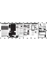
2. Removal of Color Picture Tube Unit
Place the Unit face down on a soft cloth before removing the Color
Picture Tube Unit.
3. Removal of DVD Sub C.B.A.
A. Remove solder portions "a," "b," and "c" on the DVD Sub C.B.A.
B. Remove the DVD Sub C.B.A. while releasing the Locking Tab.
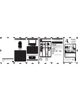
Installation of DVD Main C.B.A. and DVD Sub C.B.A.
A. Confirm that the Lever A is positioned as shown, and install the
DVD Sub C.B.A. with the Locking Tab and 2 bosses.
B. Install the DVD Main C.B.A. with the Locking Tab and the rib.
C. Solder portions "a," "b," "c" and "d" on the DVD Sub C.B.A.
Note:
Solder portions "a" and "b" while pushing down the DVD Sub
C.B.A. securely.
D. Connect the F.P.C.s to Connectors P8901, P8801 on the DVD
Main C.B.A.
Fig. D5
21
Содержание PV 20DF63
Страница 1: ...ORDER NO MKE0303602C1 B6 B22 TV DVD Combination PV 20DF63 PV 27DF63 SPECIFICATIONS 1 ...
Страница 15: ...5 1 8 WIRE AND LEAD POSITION DIAGRAM Fig 8 15 ...
Страница 18: ...Fig D2 18 ...
Страница 19: ...Fig D3 19 ...
Страница 20: ...6 1 1 1 Notes in chart 1 Removal of DVD Ass y Fig D4 20 ...
Страница 38: ...7 3 TEST POINTS AND CONTROL LOCATION 38 ...
Страница 41: ...11 2 CHASSIS FRAME SECTION 2 41 ...
Страница 42: ...11 3 CHASSIS FRAME SECTION 3 42 ...
Страница 43: ...11 4 PACKING PARTS AND ACCESSORIES SECTION 43 ...
Страница 54: ...R6012 ERJ6GEYJ561V MGF CHIP 1 10W 560 54 ...
Страница 90: ...13 2 CHASSIS FRAME SECTION 2 90 ...
Страница 91: ...13 3 CHASSIS FRAME SECTION 3 91 ...
Страница 92: ...13 4 PACKING PARTS AND ACCESSORIES SECTION 92 ...
Страница 103: ...R6012 ERJ6GEYJ561V MGF CHIP 1 10W 560 103 ...


