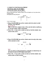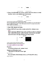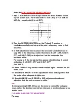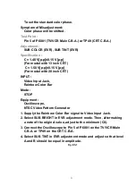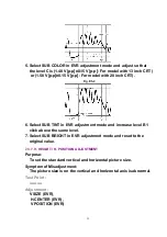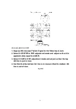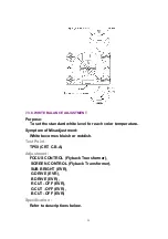
To set the standard color phase.
Symptom of Misadjustment:
Color phase will be shifted.
Test Point :
Pin 5 of P6001 (TV/VCR Main C.B.A.) or TP49 (CRT C.B.A.)
Adjustment :
SUB COLOR (EVR), SUB TINT (EVR)
Specification :
C = 1.40 V[p-p]±0.15 V[p-p]
(For model with 13 inch CRT)
C = 1.50 V[p-p]±0.15 V[p-p]
(For model with 20 inch CRT)
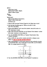
INPUT :
Video Input Jack,
Rainbow Color Bar
Mode :
STOP
Equipment :
Oscilloscope,
NTSC Video Pattern Generator
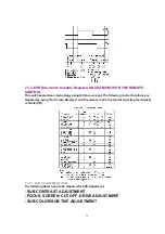
1. Supply the Rainbow Color Bar signal to Video Input Jack.
2. Select SUB BRIGHT in EVR adjustment mode. Then, after making
a note of the original value, adjust to the minimum (C0).
3. Connect the Oscilloscope to Pin 5 of P6001 on the TV/VCR Main
C.B.A. or TP49 on the CRT C.B.A.
4. Select SUB TINT in EVR adjustment mode and adjust so that level
A and B should be equal in amplitude.
Fig. E5-1
31
Содержание OmniVision PV-C1324-K
Страница 10: ...Fig 1 4 Fig 1 5 10 ...
Страница 11: ...Fig 1 6 11 ...
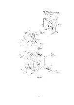
Страница 19: ...6 1 2 Disassembly Method Fig D2 19 ...
Страница 20: ...Fig D3 20 ...
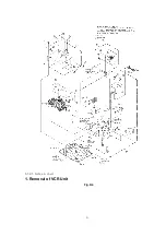
Страница 21: ...6 1 2 1 Notes in chart 1 Removal of VCR Unit Fig D4 21 ...
Страница 39: ...39 ...
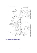
Страница 41: ...11 2 CHASSIS FRAME SECTION 1 41 ...
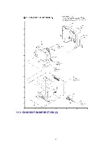
Страница 42: ...11 3 CHASSIS FRAME SECTION 2 42 ...
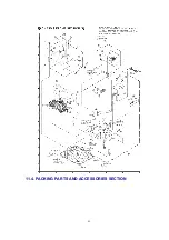
Страница 43: ...11 4 PACKING PARTS AND ACCESSORIES SECTION 43 ...
Страница 60: ...R6079 ERJ6GEYJ102V MGF CHIP 1 10W 1K 60 ...
Страница 65: ...C3035 ECJ2VC1H330J C CHIP 50V 33PF 65 ...
Страница 74: ...13 2 CHASSIS FRAME SECTION 1 74 ...
Страница 75: ...13 3 CHASSIS FRAME SECTION 2 75 ...
Страница 76: ...13 4 PACKING PARTS AND ACCESSORIES SECTION 76 ...
Страница 89: ...R554 ERDS2TJ123 CARBON 1 4W 12K 89 ...
Страница 93: ...R6013 ERJ6GEYJ102V MGF CHIP 1 10W 1K 93 ...

