6. SERVICING POSITION
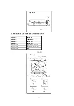
Install the Mechanism Unit on to the MAIN C.B.A..
Then fix a screw (H), and connect two frexible card Connectors
(Cylinder connector, AC Head connector) and P1531 as shown in
Fig. D5
.
Fig. D8
3.2. MECHANICAL ADJUSTMENT PROCEDURES
Refer to the Service Manual for R4-Mechanism Chassis.
(Order No. VRD0202010C8)
CAUTIONS:
To turn on the Adjustment Mode for Tape Interchangeability, set to
the service mode 2 as follows.
(Auto Tracking is turned off.)
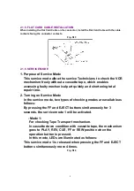
1. Press the FF and EJECT buttons simultaneously for 3 seconds.
2. Press the FF and EJECT buttons simultaneously more once to set
the Service Mode 2.
16
Содержание NV-SJ30AM
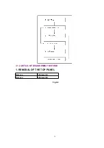
Страница 12: ...3 1 2 DETAIL OF DISASSEMBLY METHOD 1 REMOVAL OF THE TOP PANEL Remove 2 Screws A Remove 2 Screws B Fig D2 12...
Страница 13: ...2 REMOVAL OF THE FRONT PANEL UNIT Unlock 7 Tabs C Fig D3 3 REMOVAL OF THE FRONT C B A Remove 2 Tabs D Fig D4 13...
Страница 21: ...10 2 CASING PARTS SECTION 21...
Страница 22: ...10 3 PACKING PARTS SECTION 22...
Страница 23: ...11 REPLACEMENT PARTS LIST 23...
Страница 46: ...NV SJ30PMP AM EU SJ50AM EU AU FRONT C B A VEP04796A 1 A B 2 3...

